Remote Power-Off Device AP9830
Thank You! Thank you for selecting the Remote Power-Off Device (AP9830). It has been designed for many years of reliable, maintenance-free service in combination with your American Power Conversion (APC) uninterruptible power supply (UPS). APC is dedicated to the development of high-performance electrical power conversion and control products. We hope that you will find this product a valuable, convenient addition to your computing system.
Contents Overview . . . . . . . . . . . . . . . . . . . . . . . . . . . . . . . . . . . . . . . 1 Introduction 1 Features of the Remote Power-Off Device 1 Hardware requirements 2 Safety warning 2 Inventory . . . . . . . . . . . . . . . . . . . . . . . . . . . . . . . . . . . . . . . 3 Inventory 3 Server-side view of the Remote Power-Off unit 4 UPS-side view of the Remote Power-Off unit 5 Top view of the Remote Power-Off unit 5 Configuration . . . . . . . . . . . . . . . . . . . . . . . . . . . . . . . . .
Contents, continued Multiple UPS-Output Turnoff . . . . . . . . . . . . . . . . . . . . . . . . . 13 Introduction 13 Cascading multiple devices (serial setup) 13 Cascading with Matrix-UPS™ 14 Parallel setup (voltage input switches only) 14 No parallel setup for contact closure switches 15 Specifications . . . . . . . . . . . . . . . . . . . . . . . . . . . . . . . . . . . .
Overview Introduction American Power Conversion’s Remote Power-Off Device (AP9830) is an accessory that allows you to turn off the output of an APC™ uninterruptible power supply ( UPS) by a remote switch. In many facilities the UPS is not readily accessible. With the Remote Power-Off Device, you can immediately turn off the UPS output with a switch you have placed in a convenient location.
Overview continued Hardware requirements The Remote Power-Off Device requires: Safety warning Wiring safety is the responsibility of those installing the cable and remote switch. Incorrect installation can result in improper functioning of the device or damage to hardware. The use of substandard cables can produce toxic fumes in the event of a fire. 2 • An APC Smart-UPS®, Matrix-UPS™ or the Symmetra™ PowerArray™ • A switch (SELV or Class 2 circuit). See “Switch types: Table 4” on page 10.
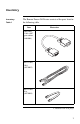
Inventory Inventory: Table 1 The Remote Power-Off Device consists of the parts listed in the following table. Item Illustration DB9-DB9 Cable (APC part number 940-0064) RJ11 Cable, 10 ft (607-0035) RJ11 Cable, 6 in.
Inventory continued Inventory: Table 1 continued Item Illustration Remote Power-Off Unit FF R-OEST WE / T PO N S UP TO TIO RA IGU NF CO w ww .a c. co m E VIC E FD -OF 0 983 ER APPOW TE MO E SR UP pc CA O/ SC E AD T U EO AD SC CA IN RP OR ER IES RV OR SEESS C TO AC Keystone Jack (750-0023) Velcro® strip for optional mounting of the Remote Power-Off unit.
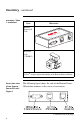
Inventory continued UPS-side view of the Remote Power-Off unit: Figure 2 The following figure shows the side of the Remote PowerOff unit that connects to the UPS. 1 2 3 4 Configuration DIP Switches DB9 Male Port – To UPS Figure 2:UPS-side view of the Remote Power-Off unit Top view of the Remote PowerOff unit: Figure 3 The top of the Remote Power-Off unit is shown in the following figure. The labels on the decal identify the components on the sides of the unit.
Configuration Overview of Configuration and Setup To install the Remote Power-Off Device, follow these steps: Configuring the device To configure the device, set the DIP switches labeled “CONFIGURATION” on the Remote Power-Off Device. Refer to the rest of this section for specific information on DIP switches. 1 Configure the device to operate in Test (Disabled) power-off mode. 2 Connect the device according to “Setup” on page 9. 3 Test the device.
Configuration continued Power-off condition — DIP switches #1 & #2: Table 2 DIP switches 1 and 2 govern the power-off condition for the Remote Power-Off Device. Refer to the table below to set DIP switches 1 and 2. Note: A contact closure switch toggles between an open and closed circuit. A voltage input switch applies and removes a voltage signal. For requirements, see “Switch types: Table 4” on page 10.
Configuration continued Power-off mode — DIP switch #3: Table 3 DIP switch 3 governs the power-off mode for Remote Power-Off Device operation. Refer to the following table for a description of the power-off modes.
Setup Introduction This section shows how to connect the Remote Power-Off Device. After setup, continue with the procedure in “Overview of Configuration and Setup” on page 6. If you are setting up multiple Remote Power-Off Devices for use with one remote switch, refer to this section for basic information on wiring and see “Multiple UPS-Output Turnoff” on page 13. Connecting the Remote PowerOff Device: Figure 4 Follow the figure below to set up the Remote Power-Off Device.
Setup continued Switch types: Table 4 The requirements and PIN assignments for the remote switch vary according to the type of switch being used: Requirements Contact Closure • Safety Extra Low Voltage (SELV) or Class 2 circuit • Switch or relay properly isolated from the utility • Latching Voltage Input 2, 5 • SELV or Class 2 circuit • Switched 24V AC/DC • Latching Table 4: Switch types Keystone jack PIN locations: Figure 5 RPO/Cascade In PIN Assignment Type 3, 4 The PIN locations for the keys
Setup continued RJ11 connector PIN locations: Figure 6 The PIN locations for the RJ11 connector appear in the figure below. Figure 6:RJ11 connector PIN locations Connecting to the keystone jack: Table 5 The following table shows how to connect the switch cable wires (26–22 AWG required) to the keystone jack. Step Action 1 Place the individual wires (unstripped) over the cylinders associated with the wiring scheme you are using (contact closure scheme shown).
Setup continued Placement of accessories The Remote Power-Off Device works effectively with all APC accessories, provided that the accessory is connected to the Remote Power-Off Device through the DB9 port labeled “TO SERVER OR ACCESSORIES.” Warning Do not connect any external APC UPS accessory between the Remote Power-Off Device and the UPS. An accessory connected between the Remote Power-Off Device and the UPS may be able to turn on the UPS during a remote poweroff condition.
Multiple UPS-Output Turnoff Introduction To set up the remote turnoff of more than one APC UPS with one switch, you must have one Remote Power-Off Device for each UPS. There are two types of setup for remote turnoff of multiple UPS outputs: • Cascading (serial) • Parallel (for voltage input switches only) Cascading multiple devices (serial setup): Figure 8 To set up either type of remote switch (contact closure or voltage input) by cascading Remote Power-Off Devices, refer to the figure below.
Multiple UPS-Output Turnoff continued Cascading with Matrix-UPS™ Do not connect more than one APC Matrix-UPS in cascade. If you are connecting a Matrix-UPS in cascade, place it at the end of the series of UPSs (UPSn in Figure 8). Parallel setup (voltage input switches only): Figure 9 To set up a remote voltage input switch by connecting multiple Remote Power-Off Devices in parallel, refer to the figure below. UPS1 UPSn POWER-OFF / TEST w w w. a p c c .
Multiple UPS-Output Turnoff continued No parallel setup for contact closure switches Do not connect more than one Remote Power-Off Device contact closure circuit to the same remote switch. Doing so may cause damage to associated equipment. To connect multiple Remote Power-Off Devices to the same contact closure switch, see “Cascading multiple devices (serial setup): Figure 8.
Specifications Remote switch requirements For remote switch requirements, see “Switch types: Table 4” on page 10. Cable requirements The Remote Power-Off Device comes with two RJ11 cables. Some users may choose to use existing building cables.
Specifications continued Product specifications: Table 6 The product specifications for the Remote Power-Off Device appear in the following table. Item Specification Size of unit (h × w × l) 2.5 × 6.1 × 9.7 cm 1.0 × 2.4 × 3.8 in Length between remote switch and unit 3 m normal, 60 m max. 10 ft normal, 200 ft max. Length between cascaded units 3 m normal, 60 m max. 10 ft normal, 200 ft max.
Limited Warranty American Power Conversion (APC) warrants the Remote Power-Off Device to be free from defects in materials and workmanship for a period of two years from the date of purchase. Its obligation under this warranty is limited to repairing or replacing, at its own sole option, any such defective products. This warranty does not apply to equipment which has been damaged by accident, negligence, or misapplication or has been altered or modified in any way.
w w w. a p c c . c o m Toll free technical support: Addresses: U. S. & Canada Austria Belgium Czech Republic Denmark Finland France Germany Holland Hungary Ireland Israel Italy Japan Luxembourg Norway Poland Portugal South Africa Spain Sweden Switzerland Turkey U. K. American Power Conversion Corporation 132 Fairgrounds Road P. O.