Wire Harness for the Battery Management System AP9924 AP9926 AP9927 Installation
Contents Preliminary Information . . . . . . . . . . . . . . . . . . . . . . . . . . . . . . . 1 Overview . . . . . . . . . . . . . . . . . . . . . . . . . . . . . . . . . . . . . 1 Silcon versus non-Silcon installation . . . . . . . . . . . . . . . . . . . 1 Inventory . . . . . . . . . . . . . . . . . . . . . . . . . . . . . . . . . . . . . 2 Safety Information. . . . . . . . . . . . . . . . . . . . . . . . . . . . . . . . . . . 3 Pre-installation Procedures. . . . . . . . . . . . . . . . . . . . . . . .
Preliminary Information Overview The Battery Management System for high voltage applications connects to one of the following: • A single APC Silcon UPS with pairs of strings. • A single non-APC UPS with single strings. The system provides battery management for nominal 2 V, 6 V, 8 V, or 12 V lead-acid batteries; or 1.2 V nickel-cadmium batteries. A system is comprised of at least one AP9921X master unit and up to five AP9921XS expansion units. Each unit supports up to 64 batteries.
Preliminary Information Inventory Item 2 Quantity Wire harness 1 Ring terminal assemblies 3 3/4 A fuse (0W2237) 2 5 A fuse ( 0W2015) 38 Tab washers 38 Male Faston® connectors 5 Female Faston connectors 37 4-inch wire tie for 5-foot harness for 50-foot harness for 100-foot harness 20 80 80 8-inch wire tie for 5-foot harness for 50-foot harness for 100-foot harness 20 40 80 Wire Harness: Installation
Safety Information Electrical Hazard Risk of electric shock: battery cabinets contain potentially lethal voltages! Batteries are energized even when AC power has been disconnected. Warning Only qualified personnel, trained in battery operation and safety, may install the harnesses. Keep unauthorized personnel away from the batteries. When installing the Battery Management System: • Cover the batteries with an insulating blanket before installing the harnesses.
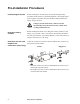
Pre-installation Procedures Lockout/Tagout the UPS Before installing the wire harnesses, use lockout and tagout safety procedures for the UPS or any attached equipment, such as high-voltage power supplies. If possible, disconnect the main output lead from the battery string to the load. Electrical Hazard Voltage is present in the battery cabinet even after disconnecting it from the main load. Use caution when working with the batteries.
Pre-installation Procedures Determine what connections you need to make: 1. If you are installing harnesses in one cabinet, connect the following: • one positive 1/2-fuse bus (+ 1/2) connector • two positive 1/2-midpoint (+ 1/2) connectors • one negative 1/2-fuse bus (- 1/2) connector 2.
Install the Wire Harnesses Before you attach the wire harnesses to the batteries, install a tab washer on the positive terminal of each battery to be managed. How you install the tab washer depends on whether the terminal bolt is embedded in the battery. How to install the tab washers on nonembedded terminals Note Do not disturb existing battery connections. Place the tab washers and nuts on top of the bolt thread extensions of the existing battery connections.
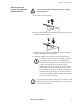
Install the Wire Harnesses How to install tab washers on embedded battery terminals Electrical Hazard Verify that the string is an open circuit before working with the batteries. mph0269a 1. Remove the bolt from a battery. mph0270a 2. Place the ring terminal on the existing battery connection, directly under the hex-head of the bolt. 3. Replace the bolt in the battery, and adjust its torque according to the battery manufacturer’s specifications. 4.
Install the Wire Harnesses Prepare the harness wires To prepare the harness wires: 1. Measure the length of each wire so that it will reach from the positive terminal on its battery to the battery connector on the rear of the Battery Management System, adding a ‘service loop’ that will permit one repair of the wire without having to replace it. 2. For an APC Silcon unit, measure wires to connect to the fuse bus and midpoint bus located on the inside roof of the battery cabinet.
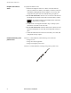
Install the Wire Harnesses Slide the receptor end of each fuse over the tab portion on the washers that you installed on the positive terminals of each battery. Note Each wire is labeled with a number indicating its correct battery connection. For example, the battery labeled 1A would connect to Battery1 of String A, and so on. mph0111a Connect the battery wires For additional guidance on battery-wire connections, see the battery connector pinout on page 13 and the battery diagram on page 14.
Additional Silcon Connection Procedures Attach harness to the fuse bus and midpoint bus (Silcon only) Install the ring terminals onto the appropriate bolts on the fuse bus and midpoint bus: 1. Remove the nut from the bolt. 2. Slide the ring terminal onto the bolt. 3. Replace and tighten the nut. See “Determine fuse bus and midpoint bus connections (Silcon only)” on page 4 for the connections to make.
Secure the Wire Harness Secure the harness to the rack or cabinet to prevent damage to the wires or personal injury by people tripping on them. Warning After the battery wires are connected, secure the harness wires. 1. Using the 4-inch wire ties, attach the battery wires to the battery straps. Attaching the wires too tightly could damage their insulation. mph0113a Caution 2. Using the 8-inch wire ties, secure the harness to the enclosure to prevent wire damage.
Connect to the Battery Management System Install the Battery Management System Install the Battery Management System in a battery cabinet, in a rack or enclosure, or on top of the battery cabinet. The system must be installed in a location that is safe, convenient, and accessible for connection procedures.
Battery Connector Pinouts Battery Connector A Battery Connector B Wire # Battery number and polarity Wire # Battery number and polarity 1 Battery 1 + 1 Battery 33 + 2 Battery 1 - and Battery 2 + 2 Battery 33 - and Battery 34 + 3 Battery 2 - and Battery 3 + 3 Battery 34 - and Battery 35 + 4 Battery 3 - and Battery 4 + 4 Battery 35 - and Battery 36 + 5 Battery 4 - and Battery 5 + 5 Battery 36 - and Battery 37 + 6 Battery 5 - and Battery 6 + 6 Battery 37 - and Battery 38 + 7 Battery
Battery Diagrams The following is an example battery diagram for two strings of 32 batteries or one string of 64 batteries. An example for one string of 32 batteries would include Connector A only.
Warranty and Service Limited warranty APC warrants the wire harness to be free from defects in materials and workmanship for a period of two years from the date of purchase. Its obligation under this warranty is limited to repairing or replacing, at its own sole option, any such defective products. This warranty does not apply to equipment that has been damaged by accident, negligence, or misapplication or has been altered or modified in any way. This warranty applies only to the original purchaser.
Life-Support Policy General policy American Power Conversion (APC) does not recommend the use of any of its products in the following situations: • In life-support applications where failure or malfunction of the APC product can be reasonably expected to cause failure of the lifesupport device or to affect significantly its safety or effectiveness. • In direct patient care.
Radio Frequency Interference a Warning Changes or modifications to this unit not expressly approved by the party responsible for compliance could void the user’s authority to operate this equipment. USA—FCC This equipment has been tested and found to comply with the limits for a Class A digital device, pursuant to part 15 of the FCC Rules. These limits are designed to provide reasonable protection against harmful interference when the equipment is operated in a commercial environment.
APC Worldwide Customer Support Customer support for this or any other APC product is available at no charge in any of the following ways: • Visit the APC Web site to access documents in the APC Knowledge Base and to submit customer support requests. – www.apc.com (Corporate Headquarters) Connect to localized APC Web sites for specific countries, each of which provides customer support information. – www.apc.com/support/ Global support searching APC Knowledge Base and using e-support.