AUTO REF/KERATO/TONOMETER Model OPERATOR’S MANUAL
NIDEK CO., LTD. (Manufacturer) : 34-14, Maehama, Hiroishi-cho, Gamagori, Aichi 443-0038, Japan Telephone: (81-533) 67-6611 Facsimile: (81-533) 67-6610 NIDEK CO., LTD : 3F Sumitomo Fudosan Hongo Bldg., 3-22-5, Hongo, (Tokyo Office) Bunkyo-Ku, Tokyo 113-0033, Japan Telephone: (81-3) 5844-2641 Facsimile: (81-3) 5844-2642 NIDEK INCORPORATED : 47651 Westinghouse Drive, Fremont, California 94539, U. S. A.
: Use this device properly and safely. BEFORE USE, READ THIS MANUAL. This operator’s manual contains information necessary for the operation of the NIDEK AUTO REF/KERATO/TONOMETER Model TONOREF II. This manual includes the operating procedures, safety precautions, and specifications. This manual is necessary for proper use. Especially, the safety precautions and operating procedures must be thoroughly understood prior to operation of the device. Keep this manual handy to verify use whenever necessary.
: Use precautions Before Use CAUTION • Do not use the device for other than the intended purpose. NIDEK is not responsible for accidents or malfunctions caused by misuse. • Be sure to read the manual prior to operation of the device to understand the safety precautions and operating procedures thoroughly. Using the device for purposes other than specified in this manual may cause unexpected malfunctions and/or adverse events. • Never modify nor touch the internal structure of the device.
: CAUTION • Do not use a power cord other than the one supplied. Also do not connect the supplied power cord to any other device. Failure or fire may result. • Do not place heavy objects on the power cord. The damaged power cord may cause fire or electric shock. • Before connecting cables to the device, turn the device off and disconnect the power cord from an outlet. Malfunction may result.
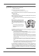
: During Use WARNING • Before starting NT measurement, set the safety stopper for each patient to prevent the air nozzle from touching the patient’s eye. Contact between the air nozzle and the eye may damage the cornea. CAUTION • Before use, perform visual and operation checks. If abnormal conditions are encountered, stop using the device. If the device is used under abnormal conditions, intended results may not occur.
: CAUTION • There may be a few constantly-lit, missing, or dead pixels in your LCD which are a characteristic of the LCD. This does not represent failure of the LCD; continuously use the display. • This device has been tested and found to comply with the limits for medical devices to the IEC 60601-1-2: 2001, and Medical Device Directive 93/42/EEC. These limits are designed to provide reasonable protection against harmful interference in a standard medical installation.
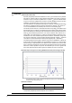
: CAUTION • Information on the avoidance of overexposure to potentially hazardous optical radiation (ISO 15004: 1997) Spectrally weighted photochemical radiances LB and LA give a measure of the potential that exists for a beam of light to cause photochemical hazard to the retina. LB gives the measure for eyes in which the crystalline lens is in place.
: After Use CAUTION • When the device is not in use, turn off the power switch and put the dust cover over the device. If not, dust may affect the measurement accuracy. • Do not yank the power cord to disconnect it from a wall outlet but hold the plug. This can damage the metal core of the cord and may result in fire, short circuit or electric shock. • Occasionally clean the prongs of the main plug with a dry cloth.
: Maintenance CAUTION • Only service technicians properly trained by NIDEK can repair the device. NIDEK is not responsible for any accidents resulted from improper servicing. • When performing maintenance work, secure sufficient maintenance space. Maintenance work in an insufficient space may result in injury.
: { Patient environment The patient environment represents a space where there is a possibility of direct contact between the patient or the operator and third person. When another type of device is used in the patient environment, use a device that complies with IEC 60601-1. If the devices that do not comply with IEC 60601-1 are used, it is necessary to use an isolating transformer as a power supply or to connect the devices to additional protective grounding. Radius of 1.5 m 2.5 m 1.5 m 1.
Table of Contents 1. BEFORE USE . . . . . . . . . . . . . . . . . . . . . . . . . . . . . . . . . . . 1 1.1 Outline of the device . . . . . . . . . . . . . . . . . . . . . . . . . . . . . . . . . . . . . . . . . . . . . . . . . . . .1 1.2 Indications for Use . . . . . . . . . . . . . . . . . . . . . . . . . . . . . . . . . . . . . . . . . . . . . . . . . . . . .2 1.3 Principles . . . . . . . . . . . . . . . . . . . . . . . . . . . . . . . . . . . . . . . . . . . . . . . . . . . . . . . . . . . . . .3 1.
: 2.8 Parameter Settings . . . . . . . . . . . . . . . . . . . . . . . . . . . . . . . . . . . . . . . . . . . . . . . . . . . . 76 2.8.1 2.8.2 2.8.3 Parameter tables . . . . . . . . . . . . . . . . . . . . . . . . . . . . . . . . . . . . . . . . . . . . . . . . . . 79 Setting the date and time . . . . . . . . . . . . . . . . . . . . . . . . . . . . . . . . . . . . . . . . . . . . 89 Entering comments. . . . . . . . . . . . . . . . . . . . . . . . . . . . . . . . . . . . . . . . . . . . . . . . . 91 3.
: 5.4 Standard Configuration . . . . . . . . . . . . . . . . . . . . . . . . . . . . . . . . . . . . . . . . . . . . . . . 120 5.4.1 5.4.2 Standard accessories . . . . . . . . . . . . . . . . . . . . . . . . . . . . . . . . . . . . . . . . . . . . . . 120 Optional accessories . . . . . . . . . . . . . . . . . . . . . . . . . . . . . . . . . . . . . . . . . . . . . . 120 6. EMC (ELECTROMAGNETIC COMPATIBILITY) . . . . . . 121 7. GLOSSARY . . . . . . . . . . . . . . . . . . . . . . . . . . . . . . . . . .
1. 1.1 BEFORE USE Outline of the device 1 AUTO REF/KERATO/TONOMETER Model TONOREF II is designed to singly perform objective refraction, corneal shape measurement, and non-contact tonometry measurement by incorporating a standard auto ref/keratometer and non-contact tonometer into one unit. The objective refraction function measures spherical powers, cylindrical powers and cylinder axis.
BEFORE USE: Indications for Use 1.2 Indications for Use The AUTO REF/KERATO/TONOMETER TONOREF II is a medical apparatus which performs measurement of the refractive errors of the eye, corneal radius of curvature and intraocular pressure.
BEFORE USE: Principles 1.3 Principles 1. Objective refraction Fine measurement beams are projected on the fundus of the patient’s eye by a projecting optical system and then computation is performed by capturing the reflected beams as a ring image to measure the refractive errors (SPH, CYL, AXIS) of the patient’s eye. 2. Corneal curvature radius measurement Four near-infrared rays area projected onto the cornea and the ray reflected by the cornea is detected.
BEFORE USE: Device Description 1.4 Device Description { Front view Function buttons LCD screen Memory indicator Start button Joystick Locking lever Power switch Cover open button Printer cover Function buttons Used to set the device and to switch the screen. Functions assigned to the function buttons are displayed by icon next to each switch on the screen. Lower two buttons on the left of the screen have unique functions when the measurement screen is displayed.
BEFORE USE: Device Description • CLR button ( ) Used to clear the measured data. When the CLR button is pressed for about a second, all the measured data is erased. • Print button ( ) When this button is pressed while the memory indicator is lit, measured results are printed out. If this button is pressed when the memory indicator is turned off, the printer paper is fed. 1 LCD screen 5.7-inch color LCD screen. The LCD screen panel pops out when the lower portion of the panel is pulled toward you.
BEFORE USE: Device Description { Rear view Eyelid detection LEDs Eye level marker Forehead rest LED for Corneal Illumination Air nozzle Measuring window Chinrest up/down buttons Safety stopper Chinrest Patient sensor PD window Forehead rest During measurements, the patient’s forehead should be gently placed over the forehead rest. Clean the forehead rest for each patient. Air nozzle Air is puffed out of the nozzle of the NT measuring unit.
BEFORE USE: Device Description Chinrest up/down buttons ( , ) Move up or down the chinrest. Safety stopper Used to provide a safety space so that the air nozzle does not touch the patient’s eye. 1 Change the position of the stopper for each patient to keep the proper amount of the space for safety. While pressing the safety stopper, “RTN TO ORG” blinks on the screen, and the measuring unit automatically returns to the origin in the right, left, back and forth directions.
BEFORE USE: Device Description { Bottom view RS-232C connector Power inlet USB-A connector Power inlet Used to connect the detachable power cord. RS-232C connector Connect an interface cable to send/receive the measured data to/from a diagnostic device or such. Target device RT-2100 series, RT-5100 LM-970, LM-990/990A, LM-1000/1000P, LM-1200 (OUT) (IN) To export the measured data to the refractor (RT), an external computer or such, connect an interface cable to this side.
BEFORE USE: Measurement Screen Description 1.5 Measurement Screen Description 1.5.1 R/K measurement screen 1 The screen for the AR (Refractive error) and KM (Corneal curvature radius) measurements has Page 1 and Page 3. The difference between Page 1 and Page 2 lies only in button icons displayed on the right of the screen. Page 1 is provided with frequently-used button icons.
BEFORE USE: Measurement Screen Description Auto button ( ) Selects the auto-tracking function and auto-shooting function. Select auto-tracking from 3D, 2D or OFF. Select auto-shooting from ON or OFF. Min. pupil mark The concentric circle displayed by eight bright points indicates the minimum measurable pupil size. If the pupil is smaller than this mark or eyelashes obscure this mark, measurement may not be possible. Measured values Displays the latest measured results.
BEFORE USE: Measurement Screen Description Focusing indicator Indicates the distance between the main body and the patient’s eye. Operate the joystick until you can obtain the proper focus ( Manual mode button ( ). ) 1 Turns off both the auto-tracking and auto-shooting functions (manual mode). The auto-tracking mark and auto-shooting mark become blank ( ), indicating that these functions are turned off. Pressing the manual mode button returns to the state before the manual mode button was pressed.
BEFORE USE: Measurement Screen Description * CS, PS, and PD data, and cataract measurement mode mark are displayed on each page.
BEFORE USE: Measurement Screen Description Eyeprint button ( ) Prints the eyeprint view of measured data. The eyeprint is printed out regardless of its parameter setting. See “2.7.2 Eyeprint” (page 74) for details on the eyeprint. 1 PD (Pupillary Distance) indication Displayed when PD (Pupillary Distance) is measured (increments: 1 mm).
BEFORE USE: Measurement Screen Description 1.5.2 NT measurement screen The following is the screen for NT (Tonometry) measurement.
BEFORE USE: Measurement Screen Description Eyelid detection mode button ( ) Used to activate the detection (eyelid detection) mode which detects whether the eyelid is over the applanation area or not. Every time the button is pressed, the eyelid detection mode is turned on or off. Whether the eyelid detection mode is turned on or off is checked by the eyelid detection cancel marker in the lower right of the screen. Indication The eyelid detection mode is cancelled.
BEFORE USE: Labels and Indications on the Device 1.6 Labels and Indications on the Device To call the operator’s attention, the device is provided with labels and indications. If labels are curling up or characters are faded and become barely legible, contact NIDEK or your authorized distributor. Indicates that important descriptions are contained in the operator’s manual and that the operator must refer to the operator's manual prior to operation.
BEFORE USE: Labels and Indications on the Device 1 [Underside view] 17
BEFORE USE: Checking Contents 1.7 Checking Contents Unpack the contents from the shipping carton and check them. The following are included in the standard configuration.
BEFORE USE: Before First Use 1.8 Before First Use Place the device on a stable table and connect a power cord to it. 1 2 1 Place the main body on a stable table. Pull the main body fully to the side on which the device is laid down, lock the main body to the base unit with the locking lever and lay the device down gently. 3 Connect the power cord to the power inlet. 4 Connect peripheral devices if necessary.
BEFORE USE: Before First Use 7 Turn the power switch on ( ). The initial screen is displayed on the LCD display and the device starts initializing. Initial screen 8 Make sure that the measurement screen is displayed. ᵏ ᴥǽᴦ ᵏᴷᴭǽǽ ǽǽǽᵈᴷᴭ ᵐᴨǽᴭᴫᴭᴭǽᵏᴮǽǽᴭᴫᴭᴭǽǽǽᴭ ᵀᴪǽᴭᴫᴭᴭǽᵏᴯǽ ᴭᴫᴭᴭǽǽǽᴭ ᴾǽǽǽǽǽᴭ Measurement screen • When the device is used for the first time, “NO PAPER” appears indicating that no paper is loaded. 9 Set the printer paper. See “4.
BEFORE USE: Before First Use { Please see here when you want to do like this. When Refer to the following. You need to know the details of the “MEASURING WINDOW CHECKING” message displayed at device start-up. “2.2.1 Measuring window check for soiling and puffed air pressure check during startup” (page 29) Auto-tracking or auto-shooting does not work depending on eye to be measured. NOTE of “2.5.
BEFORE USE: Before First Use Setting contents 22 Parameters Measurement count of NT measurement 25. NT CONTINUE Whether NT measurement values are displayed in fixed-point representation 26. DECIMAL DIGIT Measurement interval of NT measurement 27. MEAS INTERVAL Operation method of printing 31. PRINT Printing with narrow line-spacing 32. ECONO. PRINT Whether or not to erase measured data in memory just after printing 33. PRINT&CLEAR Density of printing text 34.
2. 2.1 OPERATING PROCEDURES Operation Flow Turning ON the device 2 2.2 Preparation for Measurement (page 24) Turn on the device and configure it us as necessary. Set up the patient. 2.4 Selecting the Mode (page 35) Measurement 2.5 AR (refractive error) and KM (corneal curvature radius) Measurements (page 39) { CATARACT measurement mode (page 47) { Measurement ring image display (page 48) 2.5.2 AR (refractive error) Measurement: AR Measurement Mode (page 49) 2.5.
OPERATING PROCEDURES: Preparation for Measurement 2.2 Preparation for Measurement 1 Turn the power switch on ( ). Power switch The title screen is displayed and the device is initialized. Wait for a while until the screen switches to the measurement screen. When the power is turned on, the main body makes small side-to-side and back-and-forth movements in order to determine the initial position for auto-tracking; this does not indicate malfunction.
OPERATING PROCEDURES: Preparation for Measurement 2 The measurement screen is displayed. The measurement screen with the measurement mode (R/K or NT measurement) selected just before the last shutdown is displayed. ᵏ ᴥǽᴦ ᵏᴷᴭǽǽ ǽǽǽᵈᴷᴭ ᵐᴨǽᴭᴫᴭᴭǽᵏᴮǽǽᴭᴫᴭᴭǽǽǽᴭ ᵀᴪǽᴭᴫᴭᴭǽᵏᴯǽ ᴭᴫᴭᴭǽǽǽᴭ ᴾǽǽǽǽǽᴭ 2 R/K measurement screen ᵏ ÁÖ ÁÖ ÁÐÃᴱ° NT measurement screen • “NO PAPER” is displayed on the screen if the power switch is turned on with no printer paper loaded. Load the printer paper.
OPERATING PROCEDURES: Preparation for Measurement 3: CYL mode Cylinder mode, the reading direction of cylinder data in which CYL data (cylindrical power) is represented during the measurement is selected by pressing the CYL mode button . Screen display CYL mode CYL- - reading Indicates the cylindrical power by + reading. CYL+ + reading Indicates the cylindrical power by - reading.
OPERATING PROCEDURES: Preparation for Measurement 4) Adjust the height of the chinrest by the chinrest up/down button ( , ) until the center level of the patient's eye aligns with the eye level marker. Eye level marker Before adjusting the height of the chinrest, inform the patient that the chinrest moves up and down. 2 If the chinrest is at the upper (or lower) mechanical limit, the upper limit mark (or lower limit mark ᵏ ) is displayed on the screen.
OPERATING PROCEDURES: Preparation for Measurement 7 Print the measured results. Printing operation varies according to the 31. PRINT parameter setting. 31. PRINT parameter AUTO MANUAL NO Printing method Printing starts automatically at the completion of measurement. Press the print button to print the measured data out. Printing does not occur. See “2.7 Printing” (page 71) for the details on printing. • Even when the 31. PRINT parameter is set to NO, data is exported to external connected devices.
OPERATING PROCEDURES: Preparation for Measurement 2.2.1 Measuring window check for soiling and puffed air pressure check during startup It is possible to parameter-set whether or not to check the measuring window for soiling and the pressure of puffed air before measurements. No. Parameter name Description 61 WINDOW CHECK Selection of whether or not to automatically check the measuring window for soiling from YES, NO, and DAY.
OPERATING PROCEDURES: Preparation for Measurement 2) The check result is displayed. • “PRESSURE TEST OK” is displayed: The air nozzle is clean. • If one of the following messages is displayed: After the completion of all the checks, put the TONOREF II into NT measurement mode, turn the device off once and check the air nozzle for soiling. If the air nozzle is soiled, wipe it clean of soling.
OPERATING PROCEDURES: Preparation for Measurement 6) At the completion of the checks, the screen returns to the measurement screen. • For the method of cleaning the measuring window and the air nozzle, see “4.6 Cleaning” (page 111). 2.2.2 Switching between R/K measurement and NT measurement When the measurement mode is switched from R/K measurement to NT measurement, the measuring unit inside the main body is switched. To switch the measuring unit, pull the main body fully toward the operator for safety.
OPERATING PROCEDURES: Preparation for Measurement • In RKT mode, it is possible to select the method of switching the measuring unit by setting the “72. CHANGE MODE” parameter. ᵉ ǁᵃᵆᵋᵆᵐᵅǂ When the parameter is set to AUTO, pull the main body toward operator according to the “PULL BACK” screen indication after R/K measurement is completed to switch the mode to NT mode automatically.
OPERATING PROCEDURES: Finishing the Measurements 2.3 Finishing the Measurements 2.3.1 Normal shutoff 1 Turn off ( ) the power switch. It is allowed to turn off the power with any screen displayed. 2 2 To exit measurements, inspect the measuring unit, air nozzle etc. for soiling and clean them. See “4.6 Cleaning” (page 111). 3 Put the dust cover over the device. Always keep them clean for the next use. • Be sure to put the dust cover on whenever the device is not in use. 2.3.
OPERATING PROCEDURES: Finishing the Measurements 4 When the “PACKING POSITION IS COMPLETED / SHUT DOWN PLEASE” message is displayed, turn the power switch off ( ). Ensure that the chinrest and measuring unit are at their lower mechanical limits. 5 34 ǽ ǽǽᵍᴾᵀᵈᵆᵋᵄǽᵊᵌᵁᵂ ǽ ǽᵍᴾᵀᵈᵆᵋᵄǽᵍᵌᵐᵆᵑᵆᵌᵋ ǽǽǽᵆᵐǽᵀᵌᵊᵍᵉᵂᵑᵂᵁ ᵐᵅᵒᵑǽᵁᵌᵔᵋǽᵍᵉᵂᴾᵐᵂǽ ǽ ǽ Pull the main body fully to the side on which the main body is laid down, fix the main body with the locking lever and gently lay down the device.
OPERATING PROCEDURES: Selecting the Mode 2.4 Selecting the Mode Select the measurement mode from the following options: Mode mark Auto-tracking/auto-shooting ON mark RKT button R/K button ᵏ 2 Auto button ᴥǽᴦ ᵏᴷᴭǽǽ ǽǽǽᵈᴷᴭ ᵐᴨǽᴭᴫᴭᴭǽᵏᴮǽǽᴭᴫᴭᴭǽǽǽᴭ ᵀᴪǽᴭᴫᴭᴭǽᵏᴯǽǽᴭᴫᴭᴭǽǽǽᴭ ᴾǽǽǽǽǽᴭ R/K measured data { Measurement items Select the measurements from R/K (Refractive error/corneal curvature radius) measurement and NT (tonometry) measurement. Press the RKT button to select the mode.
OPERATING PROCEDURES: Selecting the Mode AR/KM measurement mode is selected by default; there is no need to select when proceeding to measurements in AR/KM measurement mode. The items corresponding to the selected measurement mode are displayed on the screen.
OPERATING PROCEDURES: Selecting the Mode • The functions assigned to the Auto button parameter settings. depend on the 28. TRACKING SW For the setting method, see “2.8 Parameter Settings” (page 76). • When the manual mode button is pressed to turn off the auto-tracking and autoshooting modes (manual mode), the auto-tracking ON mark and auto-shooting ON mark will be blanked ( ). 2.4.
OPERATING PROCEDURES: Selecting the Mode 2.4.2 Sleep mode The device goes into sleep mode automatically to save power if no button have been pressed for a certain period of time. The time that the device goes into sleep mode can be selected from 5 minutes, 10 minutes, 15 minutes, or NO (no sleep mode) with the 64. SLEEP parameter (factory setting: 5 minutes). Sleep mode places the device into the following conditions: • The LCD display goes off. • The memory indicator blinks.
OPERATING PROCEDURES: AR (refractive error) and KM (corneal curvature radius) Measurements 2.5 AR (refractive error) and KM (corneal curvature radius) Measurements In R/K mode, three types of the measurement modes are selectable according to measurement items. Measurement item Description AR/KM measurement mode AR (refractive error) and KM (corneal curvature radius) measurements take place in a row. AR measurement mode Only the AR (refractive error) measurements takes place.
OPERATING PROCEDURES: AR (refractive error) and KM (corneal curvature radius) Measurements 1 Instruct the patient to look through the measuring window and watch the center of a picture of a balloon without straining as he or she sees it. Scenery picture with a balloon 2 Manipulate the joystick to display the patient’s eye on the screen. By pulling the joystick backward, pushing it forward, tilting it to the left and right, the main body moves back, forth, to the right, and to the left.
OPERATING PROCEDURES: AR (refractive error) and KM (corneal curvature radius) Measurements 3D auto-tracking 1) Perform rough alignment and focusing by manipulating the joystick to place in the working range of auto-tracking. Up-and-down and side-to-side alignment: Auto 2) When the device is placed within the working range of auto-tracking, it automatically starts alignment and focusing.
OPERATING PROCEDURES: AR (refractive error) and KM (corneal curvature radius) Measurements When the main body is not within the working range of auto-tracking: As the limit mark is displayed, manipulate the joystick or chinrest up/down button in the direction of the arrows. ᵏ ᵏ ᵏᴷᴭǽᴥǽᴦ ǽǽǽǽᵈᴷᴭ ᵐᴨǽᴭᴫᴭᴭǽᵏᴮǽǽᴭᴫᴭᴭǽǽǽᴭ ᵀᴪǽᴭᴫᴭᴭǽᵏᴯǽǽᴭᴫᴭᴭǽǽǽᴭ ᴾǽǽǽǽǽᴭ The level of the patient’s eye is too high from the measuring unit. Move the chinrest down to lower the level of the patient’s eye.
OPERATING PROCEDURES: AR (refractive error) and KM (corneal curvature radius) Measurements 4 Measurement starts. Measurements take place automatically when the device is best aligned and focused on the eye (when the auto-shooting function is turned on). * When the auto-shooting function is turned off, press the start button to start measurement. • The operator can start measurement by pressing the start button.
OPERATING PROCEDURES: AR (refractive error) and KM (corneal curvature radius) Measurements • If the device gets out of alignment and focus during measurement, the measurement is interrupted. If the measurement is retried, the measured results are added to the former results and stored. • To continue the measurement, press the start button again. “<>” disappears and auto-tracking starts for measurement. (except when the 31. PRINT parameter is set to AUTO).
OPERATING PROCEDURES: AR (refractive error) and KM (corneal curvature radius) Measurements +OVR Positive corneal curvature radius range over error) -OVR (Negative corneal curvature range over error) COVR (CYL range over error) 5 The corneal curvature radius is too large and over the measurable limit. The corneal curvature radius is too small and beyond the measurable limit. The cylindrical power is over the measurable limit. Measurement completes.
OPERATING PROCEDURES: AR (refractive error) and KM (corneal curvature radius) Measurements 6 Measure the other eye in the same manner. ᵉ When the other eye is set in front of the measuring unit, the measuring unit returns to the origin in the back-and-forth and side-to-side directions. ǁᵃᵆᵋᵆᵐᵅǂ When measuring a single eye only, perform NT measurement. ᵏᴷᴰǽǽᴥᴶᴦ ǽǽǽᵈᴷᴰ For the method of switching to NT measurement, ᵐᴪǽᴮᴫ° °ǽᵏᴮǽǽᴴᴫᴶᴵǽᴮᴴᴰ see “2.2.
OPERATING PROCEDURES: AR (refractive error) and KM (corneal curvature radius) Measurements { CATARACT measurement mode If cataract or abnormal eyes cannot be measured during AR (refractive error) measurement, cataract measurement mode turns on automatically. In cataract measurement mode, measurement conditions are changed so as to enhance ease of measurements of even cataract or abnormal eyes.
OPERATING PROCEDURES: AR (refractive error) and KM (corneal curvature radius) Measurements { Measurement ring image display The TONOREF II projects measurement beams on the patient’s fundus and computation is performed by capturing the reflected beams as a ring image to measure the refractive errors of the patient’s eye. The TONOREF II displays this ring for the operator to observe the patient’s eye. 1 Perform normal measurement.
OPERATING PROCEDURES: AR (refractive error) and KM (corneal curvature radius) Measurements AR (refractive error) Measurement: AR Measurement Mode 2.5.2 Perform AR measurement in the same manner as AR/KM measurement mode. KM (corneal curvature radius) measurement is not performed; KM-measured data is not displayed on the screen.
OPERATING PROCEDURES: AR (refractive error) and KM (corneal curvature radius) Measurements Error messages are the same as those for of AR/KM measurement mode. See “2.5.1 AR (refractive error) and KM (corneal curvature radius) measurements: AR/KM measurement mode” (page 39) for details. 2 Measurement completes.
OPERATING PROCEDURES: AR (refractive error) and KM (corneal curvature radius) Measurements KM (corneal curvature radius) Measurement: KM Measurement Mode 2.5.3 Perform KM measurement in the same manner as AR/KM measurement mode.
OPERATING PROCEDURES: AR (refractive error) and KM (corneal curvature radius) Measurements Error messages are the same as those for of AR/KM measurement mode. See “2.5.1 AR (refractive error) and KM (corneal curvature radius) measurements: AR/KM measurement mode” (page 39) for details. 2 Measurement completes. When the specified number of KM measurements is performed, the measurement automatically completes.
OPERATING PROCEDURES: AR (refractive error) and KM (corneal curvature radius) Measurements 2.5.4 CS (Corneal Size) Measurement 1 Press the CS/PS/PD button measurement mode. to enter CS ᵏ ᴹᵀᵌᵏᵋᵂᴾᵉǽᵐᵆᵗᵂᴻ “<>”, guide lines and “START SW: CAPTURE” are displayed on the screen. Pressing the CS/PS/PD button switches the mode in the following order: CS→ PS→ PD→ CS→ ... ᵐᵑᴾᵏᵑǽᵐᵔǽᴷǽᵀᴾᵍᵑᵒᵏᵂ 2 Guide lines 2 Manipulate the joystick to perform alignment and focusing of the patient’s eye.
OPERATING PROCEDURES: AR (refractive error) and KM (corneal curvature radius) Measurements 6 Press the right button or left button to align the guide line with the left end of the patient’s cornea. ᴹᵀᵌᵏᵋᵂᴾᵉǽᵐᵆᵗᵂᴻ Move the guide line to the left end of the patient’s cornea. 7 Press the start button to confirm the measurement. ᴹᵀᵌᵏᵋᵂᴾᵉǽᵐᵆᵗᵂᴻ A CS value (0.1 mm increments) is displayed in the lower part of the screen. 8 Press the start button again, measure the other eye in the same manner.
OPERATING PROCEDURES: AR (refractive error) and KM (corneal curvature radius) Measurements PS (Pupil Size) Measurement 2.5.5 This is the procedure to measure the pupil size (PS). To measure PS continuing from CS (Corneal Size) measurement, start from Step 5. • If the mode is switched to PS measurement mode from when a still image is displayed on the CS (Corneal SIze) measurement screen, a still image is displayed. • When recapturing the patient’s eye after turning on or off the lamp button start button.
OPERATING PROCEDURES: AR (refractive error) and KM (corneal curvature radius) Measurements 5 Press the right button or left button to align the guide line on the right of the patient’s pupil. ᴹᵍᵒᵍᵆᵉǽᵐᵆᵗᵂᴻ ᵉᴾᵊᵍᴷᵌᵋ The guide line to be aligned is displayed in pink 6 Press the down button selected guide line. to change the The left guide line is displayed in pink. Each time the switch is pressed, the guide line is displayed in pink right and left, alternately.
OPERATING PROCEDURES: AR (refractive error) and KM (corneal curvature radius) Measurements 2.5.6 PD (Pupillary Distance) Measurement { Auto-PD measurement When the 63. AUTO PD parameter is set to YES, at the ᵉ moment where measurement of both eyes is completed, ǁᵃᵆᵋᵆᵐᵅǂ PD measurement is also completed and then the PD value is displayed. Also, the near PD is automatically calculated. 2 ᵏᴷᴰǽǽᴥᴶᴦ ǽǽǽᵈᴷᴰ ᵐᴪǽᴮᴫ° °ǽᵏᴮǽǽᴴᴫᴶᴵǽᴮᴴᴰ ᵀᴪǽᴭᴫᴴᴲǽᵏᴯǽǽᴴᴫᴲᴶǽǽᴵᴰ ÐĶ² ᴾǽǽǽǽǽᴯ The PD value is displayed.
OPERATING PROCEDURES: AR (refractive error) and KM (corneal curvature radius) Measurements 3 After proper alignment of the right eye and left eye, press the Start button each time. ᴹᵍᵁᴻ ᵉ Auto-tracking and auto focusing function are turned off automatically, however when in the PD measurement mode, the focusing indicator is displayed.
OPERATING PROCEDURES: AR (refractive error) and KM (corneal curvature radius) Measurements 2.5.7 Measuring Hard Contact Lenses To measure hard contact lenses, use the provided CL holder. The contact lens holder is incorporated in the spherical model eye. The CL holder is integral with the spherical model eye. 1 Fill the concave top of the CL holder with water Pipette Use a commercial pipette to fill the concave top of the CL holder completely with water.
OPERATING PROCEDURES: AR (refractive error) and KM (corneal curvature radius) Measurements 4 5 Place the model eye/CL holder with the surface of the contact lens to be measured facing toward the measuring window and insert the fixing pins. Select the KM measurement mode and measure the lens in the same manner as KM measurement. • When measuring the convex surface of a contact lens, axis angle can be read directly. When measuring the concave surface, however, the measured axis should be read inversely.
OPERATING PROCEDURES: NT (Tonometry) Measurement: NT Mode 2.6 NT (Tonometry) Measurement: NT Mode During NT measurement, the types of the target and focusing indicator are parameter (74. TARGET TYPE) -selectable from two options: RKT During the R/K and NT measurements, the same target and focusing indicator are displayed (Factory setting). AR/NT During the NT measurement, a special alignment target and focusing indicator are displayed.
OPERATING PROCEDURES: NT (Tonometry) Measurement: NT Mode 3 Set the safety space between the patient’s eye and air nozzle with the safety stopper. WARNING • Before the measurement, be sure to set the safety stopper. The air nozzle may touch and scratch the cornea. 1) Pressing the safety stopper*1, operate the joystick so that the air nozzle approaches the cornea slowly. While pressing the safety stopper, “RTN TO ORG” blinks on the screen.
OPERATING PROCEDURES: NT (Tonometry) Measurement: NT Mode 5 Manipulate the joystick to display the patient’s eye on the screen. By tilting the joystick to the right and left, the main body moves right, left, back and forth. By turning the upper part of the joystick, the measuring unit moves up and down. Align the eye position to the measuring point with right, left, up and down movements. Adjust the focus with back and forth movements.
OPERATING PROCEDURES: NT (Tonometry) Measurement: NT Mode • When the 74. TARGET TYPE parameter is set to AR/NT, the indications on the screen are as shown on the right. ᵏ The indication of the applanation area and focusing indicator is different from the one displayed when the parameter is set to RKT.
OPERATING PROCEDURES: NT (Tonometry) Measurement: NT Mode • The device may not perform correct measurement when the eyelashes or eyelid is in the applanation area. In such cases, instruct the patient to open his or her eye wider. If the patient cannot open wider, lift the patient's lid, paying attention not to press against the eyeball.
OPERATING PROCEDURES: NT (Tonometry) Measurement: NT Mode AR/NT type RKT type Too close to the patient’s eye Pull the joystick backward to move the main body away from the patient’s eye. Optimal state Push the joystick forward to move the main body toward the patient’s eye. Too far from the patient’s eye 8 Start the measurement. • When the auto-shooting function is on: The measurement takes place automatically when the device is best aligned and focuses on the eye.
OPERATING PROCEDURES: NT (Tonometry) Measurement: NT Mode • If the measurement was not performed correctly for some reasons, an abbreviated error message is displayed above the measurement range indication. In this case, eliminate the cause of the error, following the suggestions in the table below and perform the measurement again. Error message ALM (Alignment error) APL (Applanation error) Description Alignment is not proper.
OPERATING PROCEDURES: NT (Tonometry) Measurement: NT Mode { If the “CHECK THE EYE” error occurs: Check the condition of the patient’s eye. If the patient cannot open the eye wide or eyelashes are over the applanation area, you have to help the patient open the eye wide. For a watery eye, have the patient blink his or her eyes, or wipe the tears. The error is cleared when normal measured data is obtained. Eyelid is over the applanation area. Eyelashes are over the applanation area.
OPERATING PROCEDURES: NT (Tonometry) Measurement: NT Mode 11 Pull the joystick backward once and move the main body to the other eye. The measured eye indicator of the other eye blinks and the measuring unit returns to the origin in the back-and-forth and side-to-side directions. ᵉ ǽ ǽ ᴮᴲǽǽǽ ᴮᴱ ǽ ᴮᴲǽǽǽ ᴮᴱ ǽ ᴮᴰǽǽǽ ᴮᴱ ÁÐÃᴱ° ǽ ÁÖᴮᴱ®ᴭǽ ÁÖᴮᴱ®ᴭ ¯ µ ¯µ 12 Measure the intraocular pressure of the other eye 2 ᵉ in the same way as Steps 5 to 10.
OPERATING PROCEDURES: NT (Tonometry) Measurement: NT Mode 2.6.1 Eyelid detection mode With this mode, the device always checks the eye for the amount of eye-opening and the measurement takes place automatically only when the eyelid is opened wide. { Activating and cancelling eyelid detection mode Press the eyelid detection mode button to activate or cancel the mode. ᵏ When eyelid detection mode is canceled, the eyelid detection cancel marker “ ” is displayed in the lower right of the screen.
OPERATING PROCEDURES: Printing 2.7 2.7.1 Printing Printing measured data Measured data is printed out by pressing the print button after measurement. Printing completes with paper still attached so that it does not fall. Tear off the paper to detach. • When the 31. PRINT parameter is set to AUTO, printing starts automatically when the measurements of both eyes complete. AR measurement is completed when <> is displayed.
OPERATING PROCEDURES: Printing Patient No.
OPERATING PROCEDURES: Printing * 1 Vertex distance The distance between the corneal vertex to the posterior surface of spectacle lenses. * 2 Near working distance Used for near PD calculation. Changeable in the 35 to 70 cm or in the 14- to 28-inch range by the corresponding parameter. * 3 Confidence index One of six confidence indexes (9, 8, 7, 6, 5 or E) is printed out. E is erroneous data. The higher the confidence index, the higher the reliability of measured data.
OPERATING PROCEDURES: Printing * 10 PD for near vision PD for a near working distance of 40 cm (factory setting). Use it for prescriptions of reading glasses or bifocals. * 11 Comments It is possible to enter the desired letters or symbols. See “2.8.3 Entering comments” (page 91) for the entering method. 2.7.2 Eyeprint Aside from normal printing, the eyeprint button serves to print the eyeprint and PD value only based on the AR median values or latest values.
OPERATING PROCEDURES: Printing 2.7.3 Printing parameter settings The present parameter settings, set time, comments and maintenance program versions are printed out. 1 Press the parameter button for about a second. The PARAMETER SETTING screen is displayed. The parameter No. and parameter names are displayed. See “2.8 Parameter Settings” (page 76) for details on the parameters. 2 Press the print button 2 . The parameter settings are printed as in the right.
OPERATING PROCEDURES: Parameter Settings 2.8 Parameter Settings The TONOREF II is provided with parameters that set various functions according to the user’s usage pattern. The procedure for checking and changing the parameter settings is explained. 1 Press the parameter button ond. for about a sec- 㧼㧭㧾㧭㧹㧱㨀㧱㧾ޓޓ㧿㧱㨀㨀㧵㧺㧳 㧭㧾 㧷㧹 㧺㨀 㧼㧾㧵㧺㨀㧝 㧼㧾㧵㧺㨀㧞 㧼㧾㧵㧺㨀㧟 㧲㨁㧺㧯㨀㧵㧻㧺㧝 㧲㨁㧺㧯㨀㧵㧻㧺㧞 㧯㧻㧹㧹㨁㧺㧵㧯㧭㨀㧵㧻㧺 㧯㧸㧻㧯㧷ޓ㧿㧱㨀 㧯㧻㧹㧹㧱㧺㨀ޓ㧿㧱㨀 The PARAMETER SETTING screen is displayed and parameter items are displayed.
OPERATING PROCEDURES: Parameter Settings 3 Press the execute button [PRINT1] screen. to switch to the Parameters and their settings are displayed. A parameter that is being selected is highlighted.
OPERATING PROCEDURES: Parameter Settings To change the page of parameter: Page up button Page down button 6 7 8 Displays the previous page. Displays the next page. Repeat Steps 4 to 5 to change the desired parameter settings. To finish setting the parameters, press the exit button . The screen returns to the step1 PARAMETER SETTING screen. To finish setting the parameters, press the exit button again. The set parameter settings are saved even after power-off.
OPERATING PROCEDURES: Parameter Settings 2.8.1 Parameter tables [AR (AR measurement)] * Underlined options indicate factory settings. No. Parameter Settings 1 STEP 0.01D / 0.12D / 0.25D 2 VERTEX D. 0.00mm / 10.50mm / 12.00mm / 13.75mm / 15.00mm / 16.50mm 3 AXIS STEP 1°/ 5° 4 MEAS MODE CON. / NOR.
OPERATING PROCEDURES: Parameter Settings 7 : AR THUMBNAIL Selects whether or not to display the thumbnail screen of the measurement ring image during AR measurement. When YES is selected, a thumbnail of the measurement ring image is displayed to the left of the screen after AR measurement is complete. Press the ring image enlargement button for full screen display of the ring image. [KM (KM measurement)] * Underlined options indicate factory settings. No.
OPERATING PROCEDURES: Parameter Settings 22 : LOW CONF LV (Display of confidence level) Setting of how to express the level of low confidence data when the 22. SET LOW CONF parameter is set to YES. YES The level is expressed by “*3” to “*1”. The smaller the number is, the lower the confidence of the data becomes. NO Low confidence data is marked by “*” regardless of the level of confidence.
OPERATING PROCEDURES: Parameter Settings [PRINT1 (Print setting 1)] * Underlined options indicate factory settings. No. Parameter Settings 31 PRINT MANUAL / AUTO / NO 32 ECONO. PRINT YES / NO 33 PRINT&CLEAR YES / NO 34 PRINT DENCITY LOW / MIDDLE / HIGH 35 PATIENT NO. YES / NO 36 SET PATIENT NO. 0001 to 9999 37 NAME PRINT YES / NO 38 DATE FORMAT Y/M/D / M/D/Y / D/M/Y / NO 39 PRINT COMMENT YES / NO 31 : PRINT (printing) Selects the method of starting printing.
OPERATING PROCEDURES: Parameter Settings 38 : DATE FORMAT (date format) Selects the format of date. Y/M/D Year, Month, Date M/D/Y Month, Date, Year D/M/Y Date, Month, Year NO No printing 39 : PRINT COMMENT Selects whether or not to print comments. 2 [PRINT2 (Print setting 2)] * Underlined options indicate factory settings. No. Parameter Settings 41 AR PRINT ALL / SHORT 42 KM PRINT ALL / SHORT / ALL(KM) 43 CONF.
OPERATING PROCEDURES: Parameter Settings 44 : ERROR DATA Selects whether or not to display and print erroneous data obtained during AR measurement. When this parameter is set to YES and the measured data is erroneous, the data is displayed in yellow and “Err” is printed before the measured data. • When the 43. CONF. INDEX parameter is set to YES, “E” is printed out as a confidence index. 45 : CAT MARK (cataract mark) Selects whether or not to add “ measurement mode.
OPERATING PROCEDURES: Parameter Settings [PRINT3 (Print setting 3)] * Underlined options indicate factory settings. No. Parameter Settings 51 SE PRINT YES / NO 52 EYE PRINT YES / NO 53 TL PRINT YES / NO 54 CL PRINT YES / NO 55 NEAR PD PRINT YES / NO 56 WORKING D.
OPERATING PROCEDURES: Parameter Settings [FUNCTION 1 (Various functions 1)] * Underlined options indicate factory settings No.
OPERATING PROCEDURES: Parameter Settings 66 : AR BRIGHTNESS (light intensity of AR measurement screen) Brightness of the LCD screen during the ARK measurement. Select the brightness from NORMAL or LIGHT. 67 : NT BRIGHTNESS (light intensity of NT measurement screen) Brightness of the LCD screen during the NT measurement. Select the brightness from NORMAL or LIGHT. 68 : ICON OFF (icon display) Selects whether to display the icon buttons on the measurement screen. YES 2 Touch icons are not displayed.
OPERATING PROCEDURES: Parameter Settings 73 : CHANGE SPEED (Measurement changeover speed) Setting of the time period required when the measurement mode is switched from the R/K measurement to the NT measurement in RKT mode. HIGH About ten seconds LOW About six seconds 74 : TARGET TYPE (Target type) Selection of the type of the target and focusing indicator that are displayed in NT measurement mode. RKT AR/NT During the R/K and NT measurements, the same focusing indicator is displayed.
OPERATING PROCEDURES: Parameter Settings 2.8.2 Setting the date and time When the date and time of the printout is not correct, set the correct date and time. • If the device is not turned on for three weeks, the date and time may be shifted. 1 Press the parameter button second. for about a The PARAMETER SETTING screen is displayed. 2 3 Press the down button SET parameter. to select the CLOCK Press the set button time setting mode.
OPERATING PROCEDURES: Parameter Settings 4 Press the up button or down button move the highlight to an item to be changed. to 㧼㧭㧾㧭㧹㧱㨀㧱㧾ޓޓ㧿㧱㨀㨀㧵㧺㧳 ޓޓޓޓޓ㨇㧯㧸㧻㧯㧷㨉 㧞㧜㧜㧣 㧛㧜㧠 㧛㧞㧠ޓ㧝㧣㧦㧜㧜 5 Press the right button or the left button Right button Increases the number. Left button Decreases the number. to change the setting. To change the time format: Change the time format between the 24-hour and 12-hour. / Changes the date format in the order of Y/ M/ D, M/ D/ Y, D/ M/ Y...
OPERATING PROCEDURES: Parameter Settings 2.8.3 Entering comments Comments to be printed can be changed (factory setting: “NIDEK TONOREF II”). 1 Press the parameter button second. for about a The PARAMETER SETTING screen is displayed. 2 3 Press the down button SET parameter. to select the COMMENT Press the set button ment setting mode.
OPERATING PROCEDURES: Parameter Settings 4 Press the right button or left button to select the position where a character is entered or changed The cursor indicates the position where a character is entered or changed. Up to 24 characters can e entered in two lines. 㧼㧭㧾㧭㧹㧱㨀㧱㧾ޓޓ㧿㧱㨀㨀㧵㧺㧳 ޓޓ㨇㧿㧱㨀ޓ㧯㧻㧹㧹㧱㧺㨀㨉 ޓ㧍̍㧏㧐㧑㧒 ̉ ޓ㧖㧗 㧙 㧚 㧜㧝㧞㧟㧠㧡㧢㧣 㧤㧥㧦㧧㧨㧩㧪㧫㧬㧭㧮㧯㧰㧱㧲㧳㧴㧵㧶㧷㧸㧹㧺㧻 㧼㧽㧾㧿㨀㨁㨂㨃㨄㨅㨆㨇㩯㨉㨊㨋 㧯㧻㧹㧹㧱㧺㨀㧦 ޓޓޓޓ㧺㧵㧰㧱㧷 ޓ㨀㧻㧺㧻㧾㧱㧲ޓ㧵㧵 Move the cursor to the desired position.
3. OPERATION WHEN PERIPHERAL DEVICES ARE CONNECTED The TONOREF II exports data to an external device such as NIDEK motorized refractor (hereafter referred to as the RT), computer, and Eye Care card system. The TONOREF II also imports data from the NIDEK lensmeter (hereafter referred to as the LM). CAUTION • Before connecting cables to devices, turn the devices off and disconnect the power cord from an outlet. Malfunction may result. 3.1 3.1.
OPERATION WHEN PERIPHERAL DEVICES ARE CONNECTED: Connecting to the NIDEK Motorized Refractor (RT) or Computer 3.1.2 Connecting procedure 1 Connect the RT (or a computer) to the data output port ( via an interface cable (optional). ) of the TONOREF II Connect the cable with the device laid down. Attach a ferrite core (optional) to the interface cable connector of the TONOREF II. Ferrite core (optional) RS-232C cable (optional) To RT or computer 3.1.
OPERATION WHEN PERIPHERAL DEVICES ARE CONNECTED: Connecting to the NIDEK Auto Lensmeter 3.2 Connecting to the NIDEK Auto Lensmeter (LM) 3.2.1 Outline The TOFOREF II imports data measured with the NIDEK lensmeter, and prints the LM data (lensmeter readings). It also exports the LM data to the connected RT. (The lensmeter provided with this function is needed.
OPERATION WHEN PERIPHERAL DEVICES ARE CONNECTED: Connecting to the NIDEK Auto Lensmeter (LM) Interface cable (optional) To LM Ferrite cores (optional) 3.2.3 To RT Operating procedure 1 After lens measurement with the LM, press the print button on the LM. 2 The TONOREF II receives lensmeter readings from the LM. • When the device communicates with the LM, set the communication parameters of each instrument as follows. See the operator’s manual for the setting method of each device.
OPERATION WHEN PERIPHERAL DEVICES ARE CONNECTED: Connecting to the Eye Care Card System 3.3 Connecting to the Eye Care Card System 3.3.1 Outline Data transfer by way of the Eye Care card using the optional Eye Care card system “EyeCa-RW” is explained. The Eye Care card system should be connected to the data output port ( ) provided at the bottom of the device. For the DIP switch settings, only set SW3 of the DIP switchpack of the Eye Care card system located at the bottom to the “ON” position.
OPERATION WHEN PERIPHERAL DEVICES ARE CONNECTED: Connecting to the Eye Care Card System 3.3.3 Transferring data with the EyeCa-RW The procedure for writing data to the Eye Care card differs depending on whether the measured data is printed or not. { When printing measured data 1 Insert the Eye Care card into the TONOREF II on condition that the TONOREF II has no measured data in the internal memory. The EyeCa-RW emits a short beep and the access indicator illuminates in green.
OPERATION WHEN PERIPHERAL DEVICES ARE CONNECTED: Connecting to the Eye Care Card System { When not printing measured data Set the 39. PRINT parameter to “MANUAL” or “NO” in advance. See “2.8 Parameter Settings (Page 76)” for details. 1 After measurements, insert the Eye Care card. The EyeCa-RW emits a short beep and the access indicator illuminates in green. The access indicator changes to the orange one, and the data is written to the Eye Care card.
OPERATION WHEN PERIPHERAL DEVICES ARE CONNECTED: Connecting to the Eye Care Card System 100
4. 4.1 MAINTENANCE Troubleshooting In the event that the device does not work correctly, correct the problem according to the following table before contacting NIDEK or your authorized distributor. Symptom Remedy • The power cord may not be correctly connected. The LCD display does not turn on. Reconnect it securely. • The power switch may not have been turn on. Check the power switch. The LCD display does not turn on (not • The sleep function may have been executed.
MAINTENANCE: Troubleshooting Symptom Remedy • The auto-tracking function or auto-shooting function may not have been turned on. Turn them on with the auto button . • Room illumination may be reflecting on the cornea. Change the location and try measurement again. • The auto-tracking function or auto-shooting function may not work on some eyes such as keratoconus or recently-operated cornea. The auto-tracking function or autoshooting function does not work.
MAINTENANCE: Error Messages and Countermeasures 4.2 Error Messages and Countermeasures If one of the following error codes is displayed on the screen or printed out, follow the suggestions in the cause and countermeasure column. The error code, detailed indications and serial number of your device are helpful in proper servicing.
MAINTENANCE: Error Messages and Countermeasures Error code Cause and countermeasure • Error related to control signals for communication (input port) ERR021 Ensure that the interface cable is properly connected to the input port. • Also ensure that the communication parameters are properly set. • Error related to control signals for communication (input port) ERR022 Ensure that the interface cable is properly connected to the input port.
MAINTENANCE: Error Messages and Countermeasures Error code Cause and countermeasure • Error related to the movable prism. ERR051 A malfunction of the movable prism motor, movable prism sensor, electric circuit board, or a break in a cable is probable. • Shut off the device and contact NIDEK or your authorized distributor. • Error related to the movable prism. ERR052 • A malfunction of the movable prism motor, movable prism sensor, electric circuit board, or a break in a cable is probable.
MAINTENANCE: Replacing Printer Paper 4.3 Replacing Printer Paper When a red line appears on the side of printer paper, it means that paper is running short. In such a case, stop using the printer and replace printer paper with new one. • Do not run the printer when printer paper is not loaded. It may ruin the printer head. • Do not pull the paper in the printer forcefully. This may cause malfunction of the printer. 1 2 Press the cover open button to open the printer cover.
MAINTENANCE: Replacing Printer Paper 3 Insert new printer paper. Load printer paper as shown in the picture on the right. Set printer paper so that its end is exposed from the cover. • If the roll is loaded in such a way that paper becomes upside down, it is not possible to print data out. • Be sure that printer paper is not loaded in a tilted position, the core of the roll is properly placed, or there is no slack in the roll. Printer paper may not be fed properly.
MAINTENANCE: Fixing Chinrest Paper 4.4 Fixing Chinrest Paper 1 Disconnect the two fixing pins from the chinrest. 2 Remove a proper number of chinrest papers from the pack. It is impossible to fix the whole pack of chinrest paper. Be sure to fix a stack with a thickness of 6 mm of less. Pay attention not to scatter chinrest paper. 3 Pass the fixing pins through chinrest paper. Pass the fixing pins through both holes of the stack of paper.
MAINTENANCE: Checking the AR/KM Measurement Accuracy 4.5 Checking the AR/KM Measurement Accuracy To check the accuracy of measured data, use the provided spherical model eye for R/K measurement. The spherical model eye is incorporated with a contact lens holder. 1 Remove the two fixing pins and remove the stack of chinrest paper from the chinrest.
MAINTENANCE: Checking the AR/KM Measurement Accuracy { Values marked on the labels of the spherical model eye Vertex distance Diopter (Unit: D) Corneal curvature radius (Unit: mm) • When the vertex distance is set to a value other than 12 mm (US: 13.75 mm), set the 2. VERTEX D. parameter to 12 mm (13.75 mm) before performing AR measurement.
MAINTENANCE: Cleaning 4.6 Cleaning When the cover or panel of the device becomes dirty, wipe with a soft cloth. For stubborn dirt, immerse the cloth in a neutral detergent, wring well, and wipe. Finally wipe with a dry and soft cloth. CAUTION • Never use an organic solvent such as paint thinner. It may ruin the surface of the device. • Lightly wipe the exterior of the LCD display. Do not press the LCD display using an object with a hard tip. In addition, keep magnetic objects away from the LCD display.
MAINTENANCE: Cleaning 5 Check if the window is cleaned using a penlight. If not, clean it again with new cleaning paper. Apply light with a penlight and change the view angle to check the dirt clearly. Mirre ring part Measuring window • When the 61. WINDOW CHECK parameter is set to YES or DAY, the measuring window is checked whether it is soiled at device start-up. YES⇒ The measuring window is checked at every start-up. DAY⇒ The measuring window is checked at the first start-up of the day.
MAINTENANCE: Cleaning 4.6.2 Cleaning the air nozzle • Pay attention not to let dust or foreign particles into the air nozzle during cleaning. 1 Display the NT measuring screen. 2 Check the glass part of the air nozzle from an oblique direction for dust, soiling, etc. 4 Glass part Hole of the air nozzle 3 Blow the dust, foreign particles etc. off with a blower if they are settled. 4 Gently wipe the glass part with a cotton swab dampened with alcohol.
MAINTENANCE: List of Replacement Parts 4.6.3 Cleaning the printer After repeated usage, the paper slot of the auto cutter of the printer may become soiled with powdery paper. If the powdery paper settles, malfunction of the auto cutter may result. It must be cleaned then. 1 Open the printer cover and remove the printer paper roll. See “4.3 Replacing Printer Paper” (page 106). Auto cutter 2 Apply the nozzle of a vacuum cleaner to the auto cutter to remove powdery paper.
5. 5.1 SPECIFICATIONS AND ACCESSORIES Classifications [Classification under the provision of 93/42EEC (MDD)] Class IIa The TONOREF II is classified as a Class IIa device. [Form of protection against electrical shock] Class I The TONOREF II is classified as a Class I device.
SPECIFICATIONS AND ACCESSORIES: Safety Features 5.2 Safety Features To ensure safe use, the device is provided with the following safety features. The switch detects if the main body is fully pulled toward the operator. Unless the switch is turned on, the switchover between the R/K measuring unit and NT measuring unit is disabled. This sensor detects if the patient's chin is placed on the chinrest during the up-and-down movement of the chinrest.
SPECIFICATIONS AND ACCESSORIES: Specifications 5.3 Specifications { Measurement of refractive error (AR measurement) • Spherical power (S) -30.00 to +25.00 D (V.D.=12 mm) 0.01/ 0.12/ 0.25 D increments • Cylindrical power (C) 0 to ±12.00 D 0.01/ 0.12/ 0.25 D increments • Cylinder axis (A) 0° to 180° 1°/ 5° increments • Vertex distance 0 mm/10.5 mm/12 mm/13.75 mm/15 mm/16.
SPECIFICATIONS AND ACCESSORIES: Specifications • Cylinder axis (A) 0° to 180° 1°/ 5° increments • Chart Scenery chart { PD measurement • Measurable range 30 to 85 mm (Near PD: 28 to 80 mm, Near working distance= 40 cm) 1 mm increments { CS measurement • Measurable range 10.0 to 14.0 mm 0.1 mm increments { PS measurement • Measurable range 1.0 to 10.0 mm 0.
SPECIFICATIONS AND ACCESSORIES: Specifications { Other functions • Alignment/observation method 5.
SPECIFICATIONS AND ACCESSORIES: Standard Configuration 5.4 5.4.1 Standard Configuration Standard accessories • Printer paper 3 rolls • Power cord 1 unit • Dust cover 1 unit • Model eye for R/K measurement/ contact lens (CL) 1 set holder (Integral type) 5.4.
6. EMC (ELECTROMAGNETIC COMPATIBILITY) The Electromagnetic Compatibility Directive sets the essential requirements for electrical and electronic equipment that may disturb or even be disturbed by other equipment. The TONOREF II complies with these requirements as tabled below. Follow the guidance on the tables for use of the device in the electromagnetic environment.
EMC (ELECTROMAGNETIC COMPATIBILITY) Guidance and manufacturer's declaration - electromagnetic immunity The TONOREF II is intended for use in the electromagnetic environment specified below. The customer or the user of the TONOREF II should assure that it is used in such an environment.
EMC (ELECTROMAGNETIC COMPATIBILITY) Guidance and manufacturer's declaration - electromagnetic immunity The TONOREF II is intended for use in the electromagnetic environment specified below. The customer or the user of the TONOREF II should assure that it is used in such an environment.
EMC (ELECTROMAGNETIC COMPATIBILITY) Recommended separation distances between portable and mobile RF communications equipment and the TONOREF II The TONOREF II is intended for use in an electromagnetic environment in which radiated RF disturbances are controlled.
7. GLOSSARY { Terminology related to the AR/KM measurement z AI mode In this mode, the measurement is automatically completed after three or more measurements if the data is stable without variations in the AR measurement. When unstable data is included, additional measurements are performed until stable data is obtained. z AR median values and KM median values The central value of the measurements which are put in order in the computer.
GLOSSARY: z Focusing indicator The indicator which shows the distance between the corneal center of the patient’s eye and the tip of the air nozzle. z Fogging The patient’s view is blurred so as not to allow the eye to achieve focus to eliminate accommodation. z Limit mark When the main body gets out of the working range of auto-racking, the limit marks (arrows) are displayed on the screen. z Min. pupil mark Indicates the minimum pupil size measurable.
GLOSSARY: z Vertex Distance (V.D.) The distance between the corneal vertex to the posterior surface of the spectacle lens. { Terminology related to the NT measurement z APC (Automatic Puff Control) The function which performs the normal measurement for the first time, however, in the subsequent measurements, automatically controls the air pressure in order to measure using a softer puff of air. z Applanation To flatten the cornea by pressing it with air pressure.
GLOSSARY: z Low confidence data Measured data with a “*” indication. This is displayed on the screen when measurement is performed in spite of a measurement error (APL or ALM). As the confidence of the measured data is low, this kind of measured data is called “Low confidence data”. z Measurement range The range in which measurement can be performed.
8. INDEX A Air nozzle . . . . . . . . . . . . . . . . . . . . . . . . . . . . . . . . . . . . . 6 Alignment spot . . . . . . . . . . . . . . . . . . . . . . . . . . . . . . . . 63 Applanation area . . . . . . . . . . . . . . . . . . . . . . . . . . . . . . 14 AR/KM measurement mode . . . . . . . . . . . . . . . . . . . . . 39 Auto-shooting mark . . . . . . . . . . . . . . . . . . . . . . . . . . . . 10 Auto-shooting mode . . . . . . . . . . . . . . . . . . . . . . . . . . . 36 Auto-tracking mark . . . . .
INDEX: 130