BroadBand CTEP/G Series Zero, Three, Six Battery Pole/Ground Mount Enclosures 120 V/240 V User’s Manual 990-5520A 08/02
Chapter 1 General Information The CTEP/G Series Enclosures provide housing for a power source for broadband cable operations. Safety This Safety Guide contains important instructions that should be followed during installation and maintenance of the APC equipment and batteries. It is intended for APC customers who setup, install, relocate, or maintain APC equipment. Changes and modifications to this unit not expressly approved by APC could void the warranty.
Chapter 2 Installation Only trained service personnel should install and maintain the power supply enclosure. Prior to installing the power supply enclosure, a utility breaker box must be installed on the pole. Utility line voltage must be routed to the enclosure. Local, state, federal and/or National Electric Code (NEC) regulations regarding location, permits and electrical wiring must be adhered to. Do not operate the power supply where the temperature and humidity are outside the specified limits.
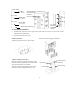
Unpacking Inspect the unit upon receipt. Notify the carrier if there is damage. The packaging is recyclable; save it for reuse or dispose of it properly. Check the package contents. The package contains the enclosure, battery cables, connectors and associated hardware and product documentation. CTEP/G3: (5 cables); 15” black battery jumpers (2), 24” black (1), 27” red (2), 34” red (1). CTEP/G6: (9 cables); 15” black battery jumpers (4), 25” black (1), 40” black (1), 60” black (1), 27” red (1), 34” red (1).
CTEP6 Model Top Hole .75” (2 cm) 12” (30 cm) Middle Hole .75” (2 cm) 12” (30 cm) Mounting Bracket is permanently attached to enclosure. Bottom Hole .75” (2 cm) 5/8” Pole Bolt and Square Washer Bottom Edge of Housing Ground Mount Installation 1. Install an APC approved concrete pad. Contact your dealer or see How to Contact APC, in this manual for more information. 2. Secure the enclosure to the pad. 0 Battery Enclosure: Attach the ground skirt to the concrete pad.
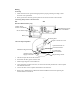
Wiring Grounding 1. Install and interconnect ground rods appropriate for proper grounding according to local electrical code requirements. 2. Route ground wires from the ground system into the bus bar located on the enclosure.
Options The CTEP/G6-120GI has an optional External AC Generator Interface. For available options see your dealer or the APC web site, www.apc.com/support. Connecting the Batteries The battery circuit breaker must OFF prior to battery installation. Use normal precautionary measures when wiring and connecting the batteries. Tape one end of each jumper cable prior to installation.
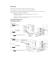
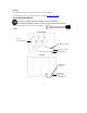
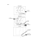
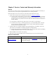
CTEP6 Bottom Shelf 60” Black to Battery 3+ 40” Black to Battery 1Middle Shelf 27” Red to Circuit Breaker 60” Black to Circuit Beaker 25” Black to CTSP 34” Red to CTSP Circuit Breaker 40” Black from Battery 6Top Shelf CTSP Battery Connection Cables from Battery 3- and Circuit Breaker 7
Chapter 3 Service, Contact and Warranty Information Service APC makes every effort to ensure parts and equipment arrive in working condition. Occasionally, it may be necessary to return parts or equipment that are not in working condition. If the UPS requires service do not return it to the dealer. Instead, follow these steps: 1. 2. Contact APC Customer Service through the APC web site, www.apc.com/support. Note the product model number, the serial number, and the date purchased.
Limited Warranty American Power Conversion (APC) warrants its products to be free from defects in materials and workmanship for a period of two years from the date of purchase. Its obligation under this warranty is limited to repairing or replacing, at its own sole option, any such defective products. To obtain service under warranty you must obtain a Returned Material Authorization (RMA) number from customer support.