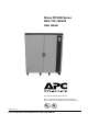
Silcon DP300E Series 480V 120–160kVA User Guide Copyright © 1999 APC Denmark A/S Due to continuous product development information given in this manual is subject to change without notice. 7OA0003 US rev. 03 User Guide Silcon DP300E Series 480V 120-160kVA 7OA0003 US rev.
IMPORTANT SAFETY INSTRUCTIONS SAVE THESE INSTRUCTIONS This manual contains important instructions for your Silcon DP300E UPS that should be followed during installation and maintenance of the UPS and batteries. WARNING! Do not stand on or place any object on any UPS cabinet or UPS cubicle due to personal and product safety. IF THE UPS IS SOUNDING AN ALARM, go to Section 6.0 To silence the audible alarm, press the silence alarm key shown at the right.
Table of Contents: 1.0 Introduction 1.1 1.2 General The display unit 2.0 Stop, Start & Operating the External Service Bypass Panel 2.1 2.2 2.3 2.4 2.5 2.6 2.7 General Stop (stand-by) Start (from stand-by) Stop (for complete power down) Start (from complete power down) Operating the external service bypass switch, single systems Operating the external service bypass switch, parallel systems 3.0 Operation 3.1 Keyboard description 4.0 Programming Parameters 4.1 4.2 4.3 4.4 4.
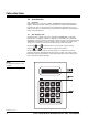
Introduction 1.0 Introduction 1.1 General Congratulations on your choice of Silcon DP300E UPS (Uninterruptible Power Supply). This UPS has been designed and produced for reliable and troublefree long-term use. For you it means that once installed and commissioned, you can forget it. However, you should arrange for preventive maintenance as described in section 8.0 of this manual. 1.2 The display unit The display unit – placed on the front of the Silcon DP300E UPS – is the link between user and UPS.
Stop, Start & Operating the External Service Bypass Panel 2.0 Stop – Start and Operating the External Service Bypass Panel 2.1 General CAUTION! To avoid possible personal injury or equipment damage, be aware that there may be AC voltage at the UPS’s output terminals/receptacles any time AC input power or DC battery voltage is applied. The UPS can provide output voltage from the batteries even when there is no AC input line voltage.
Stop, Start & Operating the External Service Bypass Panel 2.4 Stop (for complete power down) 2.4.1 Switching off Silcon DP3120E – DP3160E WARNING: If the UPS system has a service bypass panel, and if load equipment must remain ernergized from the utility, refer to operation service bypass before proceeding. WARNING: This UPS system contains a special design feature, which guarantees output voltage in the form of bypass operation.
Stop, Start & Operating the External Service Bypass Panel WARNING: Make sure that all cable con– nections are in place prior to starting-up the first time after having completed the electrical installation. NOTE: After starting-up the system first time, check that the battery temperature can be displayed. (Press 5 and 8 simultaneously on the display; if not correctly installed display will show NV (Not Valid)). It is recommended to perform a battery capacity test after having completed the installation.
Stop, Start & Operating the External Service Bypass Panel Single Utility 2.6 Operating the external service bypass switch, single systems 2.6.1 Bypassing the UPS Display shows Action 1. Press on the keyboard 2. Press or 3. Press on the keyboard 4. Press on the keyboard on the keyboard until Dual Utility Bypass operation : NO Bypass operation : YES Lamp indication on bypass panel 5.
Stop, Start & Operating the External Service Bypass Panel Single Utility 2.6.2 Switching the system from external bypass into normal UPS operation Action 1. Display shows Turn the input switch (Q001) to position “1”. If dual utility is present, turn the bypass input switch (Q010) to position “1”. **System OFF** 2. Wait 10 sec. Open the UPS front door and press the green “ON“ key Normal operation load power 0% 3. Press on the keyboard 4. Press or 5. Press on the keyboard 6.
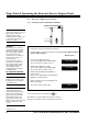
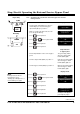
Stop, Start & Operating the External Service Bypass Panel Single Utility 2.7 Operating the external service bypass switch, parallel systems 2.7.1 Bypassing the parallel UPS system H003 Utility Load Q003 Service bypass switch H004 Q004 Action Point 1-4 can be carried out with any of the parallel systems, however this will switch all systems into bypass operation. Display shows Q002a H002a Q002b Q001b Q001a H002b 1. Press on the keyboard 2.
Stop, Start & Operating the External Service Bypass Panel 10. Turn all input switches (Q001) to position “0“. On systems with dual utility, turn bypass input switches (Q010) to position “0”. The red alarm LED below the display lights and the acoustic alarm sounds for 30 secs. * The acoustic alarm can be reset by the key EMERGENCY (UPS not alive) 1. 2. 3. 4. 5. 6. Turn the bypass switch (Q003) to position “1“. Turn the output switch (Q004) to position “0”. Turn the output switches (Q002) to position “0“.
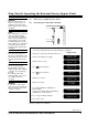
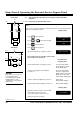
Stop, Start & Operating the External Service Bypass Panel 2.7.2 Single Utility Switching the parallel system from external bypass into normal UPS operation H003 Utility Load Q003 Service bypass switch Q004 Q002a H002a Q002b Q001b Q001a H002b Display shows Action H004 1. Check that the output switch (Q004) is in position “0” 2. Check that all output switches (Q002) are in position “1” 3. Turn input switches (Q001) to position “1” 4.
Stop, Start & Operating the External Service Bypass Panel The following can be carried out on any UPS Display shows 14. Press 15. Press on the keyboard or on the keyboard until 16. Press on the keyboard 17. Press on the keyboard All the systems will transfer to normal operation. Bypass operation : YES Bypass operation : NO Normal operation load power xx% No lamps on the bypass panel light any longer 7OA0003 US rev.
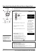
Stop, Start & Operating the External Service Bypass Panel 2.5.3 Single Utility H003 Utility Load Q003 Service bypass switch Q004 Q002a H002a Q002b Q001b In a redundant system one UPS can be isolated for service/maintenance without affecting the other parallel UPS(s). H004 H002b Q001a Isolating one UPS for service/maintenance 1. Check that the remaining UPS(s) will be able to carry the load when one UPS is isolated. 2.
Operation 3.0 Operation The display is used to show parameters, alarms/messages, and measured values. The alarm LED is used with an audible alarm to indicate unusual operating situations. The keyboard is used for programming and control of displaying parameters, alarm messages, and displaying measured values. 3.
Programming Parameters 4.0 Programming Parameters 4.1 General Some operating parameters can be programmed directly from the keyboard. Unless you are quite sure of the consequence of changing the following parameters, please contact your local APC dealer for assistance. Parameters are programmed as shown in the example 4.2.3. 4.2 Parameters 4.2.1 NOTE: The system must not run in bypass mode for extended periods of time as the batteries will not be charged.
Programming Parameters 4.2.2 Keys used for programming 4.2.3 Programming example - switch to bypass operation NOTE: The display accuracy is ±1-2%, ±1 digit. NOTE: This is only to illustrate an example. Please see chapter 2.6 - 2.7 for further details. Action 1. Press Display shows to enter parameter stack Bypass operation : NO 2. Press or 3. Press until 4. Press to store 5. Press to exit until Bypass operation : YES Bypass operation To return to normal operation Action 6.
Programming parameters 4.3 Programming of system configuration parameters The system configuration parameters are protected by a password because most of them are critical for correct operation of the system. Wrong programming can for example destroy the battery or cause loss of output voltage during operation!! 4.3.
Programming Parameters 4.3.2 Programming example – change charge voltage to 446V* * For charge voltages, battery warnings and shut down voltages, and high battery temperature, the parameter is changed by entering the actual value like example 4.3.2. NOTE: Only for APC personnel and certified local APC personnel. Action 1. Press Display shows and simultaneously to open for password input 2. Key in password : Enter password xx xx xx by pressing Last selected parameter or 3. Press 4. Press 5.
Programming Parameters 4.4 Programming of battery monitor Action 1. Display shows Press and simultaneously to open for password input NOTE: Only for APC personnel and certified local APC personnel. 2. Enter password xx xx xx by pressing 3. Press 4. Enter the expected back-up time in min. at 100% ohmic (pf = 1) load, when the inverter has a mean efficiency of approx. 96% or until Key in password : Last selected parameter Expected back-up time [min.]: XXX.X Expected back-up time [min.]: 14.
Programming Parameters 4.5 Parallel programming/operation Programming parameters for advanced parallel operation To use the advanced parallel functions the following parameters must be programmed: 1. 2. 3. 4. 5. NOTE: Common battery pack is a technical possibility. However, APC recommend separate battery pack due to a higher safety degree in connection with redundant/parallel operation. The UPS system is prepared for both solutions.
Programming Parameters Programming example – Highest Station No. Parameters are selected by pressing the C key – one or more times. Action 1. Display shows Press and simultaneously to open Key in password : for password input 2. Enter password xx xx xx by pressing Last selected parameter 3. Press or 4. Press for change 5. Press to store until Highest station address : 2 Highest station address : 3 Data stored Highest station address : 3 6.
Programming Parameters Parallel operation alarms. General. If alarms concerning the parallel operation communication arise all parallel operation functions being controlled by the advanced management will be inactive. If the advanced parallel operation functions are inactive, “only” the simple hardware control of parallel operation, which controls load sharing, operation mode, etc., is left. Alarm texts conc. parallel operation.
Measurements 5.0 Reading Out Measurements Press as indicated below one key or two keys simultaneously (values used are only random for illustration): NOTE: Utility = Mains Action Display shows 98.01.16 10.
Alarms 6.0 Alarms - What To Do 6.1 General Alarms are indicated by the red LED (above the upper left corner of the keyboard) and by a 30 secs. acoustic signal. An alarm is registered in an alarm stack as long as it is present, and logged in the same succession as they arise. IF THE UPS IS SOUNDING AN ALARM. To silence the audible alarm, press the silence alarm key shown at the right. If you do not silence the alarm, it will automatically silence itself after 30 seconds.
Alarms 6.4 The events logger The events logger is a memory stack, in which the last 250 events are stored in the same sequence as they may arise (showing the latest first).
Alarms 6.6 Possible alarms Possible alarm Description Action 1. Peak current limiter active Check for blown fuses in your installation 2. Bypass power supply fault 3. Delta current limiter active 4. Fan fault Peak current limiter has been activated and UPS switched to bypass operation. System overloaded Fault in redundant PSU for bypass.
Alarms NOTE: Utility = Mains Possible alarm Description Action 20. High temp. isolation transformer Temperature on isolation input/output transformer to high Temperature on static input switch too high Temperature on static bypass switch too high Temperature on main inverter too high Temperature on delta inverter too high The battery has been discharged to minimum permissionable level The battery is nearly decharged Check fan, check for airflow obstructions, check for overload As no. 20 21.
Alarms Possible alarm Description Action 39. System is locked in oper. mode UPS has attempted 10 times within 1 min. to switch from bypass to battery operation or “High DC warning” has appeared 10-20 times within 1 min.
Remote Display NOTE: The alarm can be reset from remote display. 7.0 Remote Display 7.1 Remote Display Operation The remote display is an inactive unit that is unable to influence the operation of the Silcon DP300E. It is impossible to adjust or influence the function of the DP300E. The alarms available on remote display are a subset of the alarms, which can be shown on the internal display. Available alarms are described in section 7.3.6. 7.1.
Remote Display NOTE: Utility = Mains Possible alarm Description Battery MCB is off Battery MCCB switch not closed or released High temp.
Preventive Maintenance 8.0 Preventive Maintenance 8.1 General The maintenance of the Silcon DP300E UPS systems should be carried out by trained service engineers. We recommend that you obtain a service and maintenance contract from APC or an APC certified and approved provider. 8.2 Fan It is recommended to replace the fans. Please contact your local APC dealer for replacement interval. 8.3 Battery 8.3.1 Control of batteries The batteries can be controlled in two ways: 1. Battery capacity test 2.
Preventive Maintenance 8.4 Battery capacity test NOTE: Expect 16 hours recharge time after a battery capacity test before full backup time is available. Actions Display shows Description 1. Press 2. Press or until Battery capacity test : xxx “xxx” is back-up time from last test – if no previous test has been performed or if the test has been aborted the display will show “???”! A battery monitor test can be performed in the same way by selecting “Battery monitor test” in the display.
Preventive Maintenance 8.5 Battery monitor test The battery monitor has two main purposes: 1. 2. To show remaining back-up time, when the UPS operates in battery operation To monitor the condition of the battery, during test or normal battery operation 8.5.1 Back-up time The back-up time in the batteries is shown in the display, when UPS runs in battery operation. The back-up time is valid for the actual load on the UPS, however, if load changes, the actual back-up time will change too.
Preventive Maintenance 8.5.4 Operation of the battery monitor The operation of the battery monitor is performed from the user stack, the related parameters are: Parameters in the user menu – Battery monitor test This parameter is used for starting or interrupting a monitor test – Battery monitor reset This parameter is used for resetting activated battery alarms – Battery monitor auto This parameter is used for enabling or disabling of the automatic monitor test.
Economy Operation 9.0 Economy Operation 9.1 General In economy operation the load is supplied directly from the utility, however the UPS is monitoring the utility and the output voltages and will in case of utility failure switch to battery operation without interruptions. NOTE: When using economy mode there is NO power factor correction on the input or regulation of output voltage.
System Specifications 10.0 System Specifications 10.
How to Contact APC 11.0 How to Contact APC For more information call: Tel: (800) 800-4APC - US & Canada Tel: (401) 789-0204 - Worldwide APC Corporate 132 Fairgrounds Road West Kingston, RI 02892 USA Tel: (401)789-0204 Fax: (401)789-3710 Internet: apcinfo@apcc.com PowerFax™: (800) 347 - FAXX APC Web site: www.apcc.com APC Denmark A/S Silcon Allé DK-6000 Kolding Tel: (+45) 75 54 22 55 Fax: (+45) 75 54 27 89 Product Support E-mail: silcontech@apcc.