® TM Computer Room Air-Conditioning—60 Hz Technical Data
Contents Overview . . . . . . . . . . . . . . . . . . . . . . . . . . . . . . . . . . . . . . . . . . . . . . . . . . . . . . . . . . . . . . 1 Scalable Solution for Critical Environments . . . . . . . . . . . . . . . . . . . . . . . . . . . . . . . . . 2 Standard Features . . . . . . . . . . . . . . . . . . . . . . . . . . . . . . . . . . . . . . . . . . . . . . . . . . . . . . . 6 Optional Features . . . . . . . . . . . . . . . . . . . . . . . . . . . . . . . . . . . . . . . . . . . . . . . . . . . . . .
ii APC NetworkAIR™ FM-DX
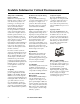
Overview The modular, Floor Mount computer room air-conditioning system offers efficient, effective and economical cooling for a variety of spaces. Computer room environmental requirements now reach far beyond the confines of the traditional data center or computer room to encompass a larger suite of applications, referred to as technology rooms.
Scalable Solution for Critical Environments Temperature and Humidity Design Conditions Maintenance of temperature and humidity design conditions is critical to the smooth operation of a technology room. Design conditions should be 72-75°F (22.224.8°C) and 45-50% relative humidity (R.H.). As damaging as the wrong maintained conditions can be, rapid temperature swings can also have a negative effect on hardware operation. This is one of the reasons hardware is left powered up, even when not processing data.
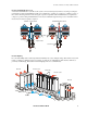
Scalable Solution for Critical Environments Dedicated Dehumidification Cycle A dedicated dehumidification cycle allows the system to increase latent capacity without overcooling, lowering the requirement for reheat and humidification. This is accomplished by operating one compressor, isolating a portion of the coil from the refrigerant flow and lowering the evaporator temperature when dehumidification is required.
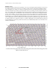
Scalable Solution for Critical Environments Humidity Control Increasing heat densities in data centers are leading to more hot spots and higher return temperatures to the precision air conditioners. When hot spots exist in close proximity to the air conditioner, temperature and humidity readings can be misleading to the overall room conditions. As temperature increases, the relative humidity (R.H.) level (the amount of moisture the air can hold at a given temperature, shown as a percentage) decreases.
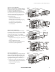
Scalable Solution for Critical Environments Glycol-Cooled Configuration Glycol-cooled systems are completely charged and factory tested in a sealed system for reliability. In mid to low ambient climates, an economizer coil can be used to increase efficiency and extend compressor life. Economizer operation greatly reduces the energy consumption of the system. Water regulating valves control head pressure.
Standard Features Double Skin Panels The frame is bolt together 12 gauge formed steel for maximum strength. Cabinet is serviceable from the front. All exterior panels and corner posts on the frame are powder coated for durability and an attractive finish. Front exterior panel crowne is 16 gauge. All other panels are double skin, 24 gauge exterior, 24 gauge interior with 1 ½ lb. (.68 kg) per cubic foot insulated for quiet operation. Insulation is CFC-free and recyclable.
Standard Features Steam Generating Humidifier The humidifier utilizes a pure steam generator specifically designed for precision environmental control. The pure steam eliminates contaminating mineral deposits, potentially harmful bacteria, white dust and excessive humidity. The humidifier requires little scheduled maintenance. Automatic flushing combined with a communication link to the controller signals when the canister is to be changed.
Optional Features Brazed Plate Condenser Water- and Glycol-cooled systems employ a brazed plate heat exchanger. The condenser is equipped with clean out plugs. Rotalock valves make removal of the brazed plate condenser easy for maintenance and replacement. Smoke Detector The factory-installed smoke detector is designed to sense smoke in the return air stream. Upon detection of smoke, an audible and visual alarm on the microprocessor will be activated and the unit will be immediately shutdown.
Optional Features Additional Programmable Input/ Output Interface Modules Each system is equipped with up to 3 additional discrete input/output modules for a total of 16 input/outputs. Each interface module is programmable with outputs that can map from any system alarm through the microprocessor controller. Inputs are capable of mapping to outputs as a system alarm or custom alarm.
Microprocessor Controller Microprocessor Controller The microprocessor controller is standard on each system. The controller provides precision control for the demanding requirements of: • Data centers • Control rooms • Clean rooms • UPS rooms Open Architecture The NetworkAIR FM protocol is open for integration with all building management systems. Communication interface on the system can be MODBUS RTU RS485.
Upflow models FM Upflow components Motor and fan assembly Electrical junction box Steam head User interface box DX coil Firestat (optional) Economizer coil (optional) Air filters Condensate pan Fan interlock switch Liquid refrigerant receiver Main power interrupt switch 3-way ball valve Display interface Brazed plate condenser (water and glycol models) Electrical panel Condensate pump (optional) Duc
Downflow models FM Downflow components Air filters Humidifier (optional) Economizer coil (optional) Condensate pump (optional) DX coil User interface box Condensate pan Firestat (optional) Motor and fan assembly Electrical panel Fan interlock switch Main power interrupt switch 3-way ball valve Display interface Liquid refrigerant receiver Steam head Brazed plate condenser (water and glycol models) Electric reheat coil (optional) Tandem compressors 12
Performance Specifications—Air Cooled NET COOLING MODE CAPACITY - BTU/HR* FM 35 80F DB, 67F WB (26.7C DB, 19.4C WB) 50% RH Total 125,000 (36.6) Sensible 110,000 (32.3) 75F DB, 62.5F WB (23.9C DB, 16.9C WB) 50% RH Total 114,000 (33.3) Sensible 110,000 (32.3) 75F DB, 61F WB (23.9C DB, 16.1C WB) 45% RH Total 114,000 (33.3) Sensible 114,000 (33.3) 72F DB, 60F WB (22.2C DB, 15.5C WB) 50% RH Total 109,000 (31.9) Sensible** 105,000 (30.9) 72F DB, 58.6 WB (22.2D DB, 14.8C WB) 45% RH Total 109,000 (31.
Performance Specifications—Air Cooled Performance Specifications - Air Cooled FM-DX AIR SYSTEM -- DIRECT DRIVE CENTRIFUGAL Air Volume -- CFM (L/s) Blower Motor -- HP (kW) External Static Pressure -- inches of water (Pa) Number of Blowers COMPRESSOR -- TANDEM SCROLL EER Quantity Nominal HP (kW) EVAPORATOR COIL -- V FRAME, COPPER TUBE/ALUMINUM FIN FM 35 FM 50 6,000 (2,830) 4 (3) 0.5 (125) 2 9,000 (4,245) 4 (3) 0.5 (125) 2 15.8 2 (tandem) 9.0 (6.71) 14.2 2 (tandem) 15.6 (11.64) 21 (1.
Performance Specifications—Water Cooled NET COOLING CAPACITY - BTU/HR* FM 35 80F DB, 67F WB (26.7C DB, 19.4C WB) 50% RH Total 134,000 (39.3) Sensible 115,000 (33.6) 75F DB, 62.5F WB (23.9C DB, 16.9C WB) 50% RH Total 123,000 (36.0) Sensible 112,000 (32.9) 75F DB, 61F WB (23.9C DB, 16.1C WB) 45% RH Total 122,000 (35.9) Sensible 122,000 (35.9) 72F DB, 60F WB (22.2C DB, 15.5C WB) 50% RH Total 117,000 (34.3) Sensible** 109,000 (32.0) 72F DB, 58.6 WB (22.2D DB, 14.8C WB) 45% RH Total 117,000 (34.
Performance Specifications—Water Cooled Performance Specifications—Water Cooled FM-DX FM 35 ECONOMIZER -- NET COOLING CAPACITY DATA -- BTU/HR (kW) @ 45F (7.2C) EWT* 80F DB, 67F WB (26.7C DB, 19.4C WB) 50% RH Total 185,000 (54.3) Sensible 141,000 (41.3) 75F DB, 62.5F WB (23.9C DB, 16.9C WB) 50% RH Total 149,000 (43.9) Sensible 129,000 (37.9) 75F DB, 61F WB (23.9C DB, 16.1C WB) 45% RH Total 146,000 (42.6) Sensible 137,000 (40.3) 72F DB, 60F WB (22.2C DB, 15.5C WB) 50% RH Total 131,000 (38.
Performance Specifications—Glycol Cooled NET COOLING CAPACITY - BTU/HR* FM 35 80F DB, 67F WB (26.7C DB, 19.4C WB) 50% RH Total 121,000 (35.6) Sensible 109,000 (31.9) 75F DB, 62.5F WB (23.9C DB, 16.9C WB) 50% RH Total 112,000 (32.6) Sensible 108,000 (31.6) 75F DB, 61F WB (23.9C DB, 16.1C WB) 45% RH Total 111,000 (32.6) Sensible 111,000 (32.6) 72F DB, 60F WB (22.2C DB, 15.5C WB) 50% RH Total 106,000 (31.0) Sensible** 104,000 (30.6) 72F DB, 58.6 WB (22.2D DB, 14.8C WB) 45% RH Total 107,000 (31.
Performance Specifications—Glycol Cooled Performance Specifications—Glycol Cooled FM-DX FM 35 ECONOMIZER -- NET COOLING CAPACITY DATA -- BTU/HR (kW) @ 45F (7.2C) EWT* 80F DB, 67F WB (26.7C DB, 19.4C WB) 50% RH Total 102,000 (29.9) Sensible 102,000 (29.9) 75F DB, 62.5F WB (23.9C DB, 16.9C WB) 50% RH Total 87,000 (25.6) Sensible 87,000 (25.6) 75F DB, 61F WB (23.9C DB, 16.1C WB) 45% RH Total 87,000 (25.6) Sensible 87,000 (25.6) 72F DB, 60F WB (22.2C DB, 15.5C WB) 50% RH Total 77,000 (22.
Electrical Data AIR COOLED REHEAT HUMIDIFIER VOLTAGE Electric Electrode Canister - Steam 230 480 208 600 OA-w/DX OA-w/DX&MultiCool MCA MOP 59.7 61.1 92.0 100.0 58.4 59.6 92.0 100.0 27.8 28.4 40.6 50.0 23.0 23.5 33.9 35.0 OA-w/DX OA-w/DX&MultiCool MCA MOP 96.1 99.7 132.2 150.0 91.3 94.5 132.2 150.0 45.5 47.0 66.4 70.0 36.5 37.8 49.7 50.0 FM 35 FM 50 WATER COOLED REHEAT HUMIDIFIER VOLTAGE Electric Electrode Canister - Steam 230 480 208 600 OA-w/DX OA-w/DX&MultiCool MCA MOP 56.6 58.0 92.
Dimensional Data na0214a FM Downflow 8.66 (220) 15.75 (400) 16.14 (410) 15.75 (400) 11.81 (300) na1017a 18.07 (459) * All dimensions are in inches (mm).
Dimensional Data na0329a FM Upflow * All dimensions are in inches (mm).
Dimensional Data APC NetworkAIR™ FM-DX 23
Dimensional Data na0205a FM Floorstand Orderable Floorstand Height Range 12” (FM35) Adjustable 10.5”-13.5” 15” (FM35) Adjustable 13.5”-16.5” 18” Adjustable 16.5”-19.5” 21” Adjustable 19.5”-22.5” 24” Adjustable 22.5”-25.
Dimensional Data FM 20” Upflow Plenum FM 24” Upflow Plenum APC NetworkAIR™ FM-DX 25
Dimensional Data na0717a FM35 12” Downflow Plenum FM50 18” Downflow Plenum 26 APC NetworkAIR™ FM-DX
Air-Cooled Condensers Air-cooled condenser—performance/electrical data OHE SKU Voltage Ambient Temperature 95F Air Quantity Fan/Motor Connection Size (inches) Weight Electrical Data Qty. HP RPM Hot Gas Liquid Lbs Kg 13,700 6,466 2 1/2 1075 1-1/8 7/8 510 231 8.7 15.0 15.0 13,700 6,466 2 1/3 1140 1-1/8 7/8 510 231 7.4 15.0 15.
Air-Cooled Condensers 2-fan air-cooled condenser APC PART CIRCUIT VOLTAGE ACCD75028 single 208-230/1/60 ACCD75029 single 208-230/3/60 ACCD75030 single 480/3/60 ACCD75031 single 600/3/60 3-fan air-cooled condenser 28 APC PART CIRCUIT VOLTAGE ACCD75036 single 208-230/1/60 ACCD75037 single 208-230/3/60 ACCD75038 single 480/3/60 ACCD75039 single 600/3/60 APC NetworkAIR™ FM-DX
Air-Cooled Condensers 2-fan air-cooled condenser APC PART CIRCUIT VOLTAGE ACCD75040 single 208-230/3/60 ACCD75041 single 480/3/60 ACCD75042 single 600/3/60 ACCD75049 single 208-230/3/60 ACCD75050 single 480/3/60 ACCD75051 single 600/3/60 4-fan air-cooled condenser APC PART CIRCUIT VOLTAGE ACCD75052 single 208-230/3/60 ACCD75053 single 480/3/60 ACCD75054 single 600/3/60 APC NetworkAIR™ FM-DX 29
Air-Cooled Condensers 2-fan low-noise condenser APC PART CIRCUIT VOLTAGE ACCD75055 single 208-230/3/60 ACCD75056 single 480/3/60 3-fan low-noise condenser 30 APC PART CIRCUIT VOLTAGE ACCD75058 single 208-230/3/60 ACCD75059 single 480/3/60 ACCD75061 single 208-230/3/60 ACCD75062 single 480/3/60 APC NetworkAIR™ FM-DX
Air-Cooled Condensers 4-fan low-noise condenser APC PART CIRCUIT VOLTAGE ACCD75070 single 208-230/3/60 ACCD75071 single 480/3/60 5-fan low-noise condenser APC PART CIRCUIT VOLTAGE ACCD75073 single 208-230/3/60 ACCD75074 single 480/3/60 APC NetworkAIR™ FM-DX 31
Fluid Coolers Glycol-cooled fluid cooler—performance/electrical data 40% Ethylene Glycol @130F Air Quantity 105F PD(ft) @GPM CFM ACFC75126 208-230/1/60 FM35 N/A 14.0@30 ACFC75198 208-230/3/60 FM35 N/A 14.0@30 OHE SKU Voltage Ambient Temperature 95F L/s Fan/Motor Connect -ion Size (inches) Weight Lbs Glycol Volume Kg Gal L Electrical Data Qty HP RPM FLA MCA MOP 20,500 9,675 3 1/2 1075 (2) 2-1/8 550 250 10.2 37.7 11.7 12.7 15.
Fluid Coolers 3-fan fluid cooler APC PART VOLTAGE ACFC75126 208-230/1/60 ACFC75198 208-230/3/60 ACFC75199 480/3/60 ACFC75129 600/3/60 2-fan fluid cooler APC PART VOLTAGE ACFC75132 208-230/1/60 ACFC75133 208-230/3/60 ACFC75134 480/3/60 APC NetworkAIR™ FM-DX 33
Fluid Coolers 3-fan fluid cooler APC PART VOLTAGE ACFC75202 208-230/3/60 ACFC75203 480/3/60 ACFC75143 600/3/60 4-fan fluid cooler 34 APC PART VOLTAGE ACFC75167 208-230/3/60 ACFC75168 480/3/60 ACFC75169 600/3/60 APC NetworkAIR™ FM-DX
Fluid Coolers 3-fan low-noise fluid cooler APC PART VOLTAGE ACFC75158 208-230/3/60 ACFC75159 480/3/60 ACFC75155 208-230/3/60 ACFC75156 480/3/60 4-fan low-noise fluid cooler APC PART VOLTAGE ACFC75164 208-230/3/60 ACFC75165 480/3/60 ACFC75161 208-230/3/60 ACFC75162 480/3/60 APC NetworkAIR™ FM-DX 35
Pump Specifications Pump performance Pump connection sizes HP (kW) 3/4 (.56) 1 (.75) 1.5 (1.1) 2 (1.5) LINE Suction Discharge Suction Discharge Suction Discharge Suction Discharge Size (inches) 1-1/4 1-1/4 1-1/4 1-1/4 1-1/4 1-1/4 1-1/2 1-1/4 Pump electrical data HP (kW) 3/4 (.56) 1 (.75) 1.5 (1.1) 2 (1.5) VOLTAGE FLA MCA FLA MCA FLA MCA FLA MCA 208/3/60 3.0 3.2 3.7 4.6 4.9 6.1 6.4 8.0 230/3/60 3.2 4.0 3.7 4.6 5.0 6.3 6.2 7.8 480/3/60 1.6 2.0 1.9 2.
Pump Specifications FM Single Pump Package FM Dual Pump Package 38 APC NetworkAIR™ FM-DX
Piping Connections Air outlets (downflow only) Main power Water/glycol out or hot gas Control interface box Water/glycol in or liquid line in UPS power MultiCool or hot water out Condensate drain MultiCool or hot water in Additional Control Access Control interface access Humidifier fill *Dimensions are shown in inches (millimeters) APC NetworkAIR™ FM-DX 39
Electrical Connections Upflow Module Controller board Downflow Module DIP switches Main circuit breaker Circuit breakers Card slot Fuses AC line reactor Input power terminal block Heater fuse block Terminal block Contactors Motor inverter/frequency controller Ground lug Control transformers Reheat SCR control Smoke detector 40 APC NetworkAIR™ FM-DX DB-9 connector/RS232 console port
Guide Specifications PART 1 — PART 1 GENERAL 1.01 SUMMARY A. The environmental control system shall be designed specifically for precision temperature and humidity control applications. It will automatically monitor and control heating, cooling, humidifying, dehumidifying, and filtering functions for the conditioned space.
Guide Specifications PART 2 — PART 2 PRODUCT 2.01 STANDARD COMPONENTS A. CABINET CONSTRUCTION 1 . Double Skin Panels:Exterior panels shall be double-wall 24 gauge metal with 24 gauge interior wall and insulated with 1.5 lb (0.68kg) density fiber insulation. Insulation shall be completely protected from the air stream by the panel wall or air blocks. Front exterior panel crown shall be 16 gauge. Front panels shall be powder coated and removable hinged with a locking handle.
Guide Specifications D. MASTER CONTROLLER 1 . Monitoring and Configuration: The master display shall allow monitoring and configuration of the precision air conditioning unit through a menu-based control. Functions include status reporting, setup, and temp/humidity set points. Four LED report the operational status of the connected Precision air conditioning unit. 2 .
Guide Specifications E. ELECTRICAL PANEL 1 . The control voltage shall be 24 VAC, class 2 circuit. The electrical panel shall contain contactors, starters, overload protection devices, and input power disconnects. The panel shall be located in the front of the unit for available access. F. EVAPORATOR COIL/94VO THERMAL CONDENSATE PAN 1 . The evaporator coil shall use aluminum fins and rifle-bored copper tubes. Coil endsupports shall be galvanized steel.
Guide Specifications L. EVAPORATOR FREEZE PROTECTION 1 . Suction pressure shall be actively monitored and controlled to eliminate the risk of condensate freeze-up on the evaporator. M. PREDICTIVE FAILURE WARNINGS 1 . Several components within the unit shall provide a warning via the microprocessor interface that service is needed prior to failure occurring. N. HIGH RETURN AIR TEMPERATURE CAPABILITY 1 .
Guide Specifications 2.02 OPTIONAL COMPONENTS A. BRAZED PLATE CONDENSER 1 . Water and glycol cooled systems shall employ a brazed plate heat exchanger. The condenser shall be equipped with clean-out plugs. Standard pressure rating shall be 450 psig (3102 kPa). B. WATER REGULATING VALVES 1 . Water and glycol cooled systems shall utilize two-way or three-way valves to regulate the amount of water or glycol supplied to the condenser in response to refrigerant discharge pressure.
Guide Specifications G. CABLE WATER DETECTOR 1 . A leak detection sensing cable shall be shipped loose with the unit. If water or other conductive liquids contact the cable anywhere along its length, the main controller visually and audibly annunciates the leak. 2 . The detector shall be provided with 20ft (6 m) of cable. Cable may be cascaded up to 500ft (152.4 m). H. ADDITIONAL PROGRAMMABLE INPUT/OUTPUT INTERFACE MODULES 1 .
Guide Specifications N. ENVIRONMENTAL MONITORING AND MANAGEMENT 1 . Environmental Monitoring Unit: A stand-alone unit shall perform continuous temperature and humidity sensing through two available proves and contact monitoring. Unit shall be controlled by available web, control console, or SNMP interface with network connection. In the event of an environmental anomaly, notification shall be sent to the customer via email or SNMP. The unit shall be 18.25”x9”x2.75”(464mm x 229mm x 70mm). 2 .
Guide Specifications PART 3 — PART 3 INDIVIDUAL SYSTEMS 3.01 AIR-COOLED A. The indoor unit shall consist of an evaporator section including evaporator coil, blower package, controls, electrical section, and compressor. B. CONDENSER 1 . Outdoor Propeller Fan Condenser: The outdoor condenser casing shall be made of aluminum, and all structural supports, coil frame, motor drive supports, and mounting legs shall be made of galvanized steel. The condenser shall have copper tubes expanded into aluminum fins.
Guide Specifications B. FLUID COOLER 1 . Outdoor Fluid Cooler: The fluid cooler casing shall be of aluminum, and all structural supports, coil frame, motor-drive supports, and mounting legs shall be made of galvanized steel. The fluid cooler coil shall have copper tubes expanded into aluminum fins. Headers and connections shall be copper. The coil shall be pressure-tested and sealed for shipment.
Guide Specifications 3.05 MULTICOOL A. Air, Water and Glycol systems shall have the option of a chilled water coil that is designed to be the primary cooling source to the backup direct expansion coil. The MultiCool (chilled water) coil shall be constructed with copper tubes and aluminum fins. It shall be located in the return air, before the V-Frame evaporator coil. The MultiCool coil shall be rated at ____BTU/ HR (kW) sensible cooling capacity with 45 F (7.2 C) entering water temperature.
Guidelines for Installation The NetworkAIR FM provides reliable, accurate temperature and humidity control of computer rooms, laboratories, and other environments that require close tolerance control. The unit incorporates the latest system design innovations to provide you with optimum efficiency, reliability, and accuracy of control. The NetworkAIR FM system will provide years of trouble-free service, when installed and maintained by technically qualified personnel.
Guidelines for Installation Receiving the unit Your NetworkAIR FM unit has been completely tested and inspected prior to shipment. To ensure that you have received the unit in excellent condition, perform a careful inspection of the crating and the unit immediately upon receipt. Verify that all parts ordered were received as specified and that the unit is the correct size and voltage necessary to fulfill your environmental control needs. Report any damage discovered to the freight carrier.
Guidelines for Installation Water supply to humidifier 1. The humidifier fill valve orifice is sized for supply water pressure from 15 PSI (103.4 kPa) to 150 PSI (1034 kPa). 2. For cases above 150 PSI (1034 kPa), install a pressure-reducing valve in the water feed line to the unit. 3. With extremely dirty or muddy water sources, proper filtration is required on the unit’s incoming water line. 4. DO NOT use softened water with the humidifier. Softened water is too conductive. 5.
® APC Worldwide Customer Support Customer support for this or any other APC product is available at no charge in any of the following ways: • Visit the APC Web site to find answers to frequently asked questions (FAQs), to access documents in the APC Knowledge Base, and to submit customer support requests. – www.apc.com (Corporate Headquarters) Connect to localized APC Web sites for specific countries, each of which provides customer support information. – www.apc.