/8 scale “Aeronca Champ” ARF Wingspan: Length: Wing Area: Weight (w/o battery): Weight (w/ PQ1800-3S): 52 in. (1320mm) 32 in. (813mm) 362 in². (23.35dm²) 28.8 oz. (816g) 33.8 oz. (958g) Pg.1 – Instructions Version 1.1, January 2009 © 2009-2010 Hobby Lobby International, Inc. All rights Reserved. • 5614 Franklin Pike Circle Brentwood, TN 37027 USA www.hobby-lobby.
Pg.2 – Instructions Version 1.
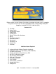
Introduction & History The full-scale Aeronca Champion, or “Champ,” was manufactured by the Aeronca Aircraft Corporation, in Middletown, Ohio between 1944 and 1951. Over 10,000 were built. In 1946, it was marketed as “the newest in aerodynamic design! . . . It’s the easiest plane you’ve ever flown. ” Like the Piper Cub with which it competed, the Champ also featured tandem seating.
Before starting, use the Contents list to take an inventory and make sure it is complete. If any parts are missing or are not of acceptable quality, contact Hobby-Lobby.
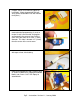
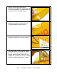
1. Prepare aileron servo mounting plate for installation. (Note: plywood tab with pullstring needs to be broken free with needle nose pliers.) 2. Turn on radio. Make sure the aileron trim is centered and all programming is reset to neutral. Install servo arm 90º to the plate and located in the center of slot. Drill the outer servo arm hole out to 3/64” (1.2mm) diameter. This hole is located 1/2” (13mm) from the center of the servo screw. 3.
5. Use tape to secure pull-string to servo wire. 6. Use needle nose pliers to break plywood tab. Carefully pull servo wire though wing section. 7. Install servo mounting plate with small sheet metal screws. 8. Remove aileron and fold CA hinges in half, as shown. Trial fit aileron in place before gluing. Careful attention should be placed on gaps at ends of aileron and tight spacing at the hinge line. Pg.6 – Instructions Version 1.
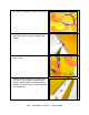
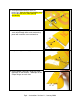
9. With the aileron tight and deflected downward, use 2 drops per hinge of thin CA to assure strong bonds. Use paper towel to remove any excess CA before drying. 10. Deflect aileron upwards and repeat application for bottom of wing. Note very small gap between aileron and wing. 11. Using a 90º triangle, mark aileron for location of control horn as shown in photo. 12. Use tape to hold aileron in neutral position. Install control horn so that holes in control horn are in line with the aileron hinge line.
13. Install pushrod and adjust clevis as necessary. Note the heat shrink tubing used here to prevent clevis from opening accidentally. 14. Install wing joiner into center section. Feed servo wire through holes and secure wing panel with machine screw and washer. 15. Repeat for opposite wing panel. 16. Install Rudder CA hinges using the same technique as the ailerons. Two drops of thin CA per hinge, on each side. Pg.8 – Instructions Version 1.
17. Install tailwheel bracket as shown in photo. 18. Install the Elevator CA hinges. Again, test fit for alignment and slight gap between the two surfaces. Note: you may wish to flex hinges back and forth several times before installation. 19. Temporarily install the wing with long machine screws and washers. 20. Test fit the tail assembly. Note the elevator is parallel to the wing and the rudder is perpendicular to the elevator. Assemble the tail section using 5-min epoxy.
21. Install screws into tailwheel bracket. 22. Turn on radio. Make sure the Elevator and Rudder trims are centered and all programming is reset to neutral. Drill the outer servo arm hole out to 3/64” (1.2mm) diameter. This hole is located 1/2” (13mm) from the center of the servo screw. Install on pushrod “z-bend” and slide each pushrod into guide tube. 23. Install servo arms at 90º to pushrod as shown in photo. Secure with servo arm screw. Mount your receiver with doublesided foam tape or Velcro. 24.
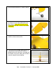
25. Install the landing gear using the nylon straps and sheet metal screws. 26. Install the wheels with a wheel collar on each side of each wheel. (Battery hatch shown installed with magnets in this photo.) 27. Solder connectors to motor, electronic speed control (ESC), and battery. Install motor on firewall per your motor’s instruction manual. Right and down thrust is already built into firewall, so you can mount motor flat against firewall. 28.
29. Install servo wires into your receiver. Make sure all items are secure for flight. Install wing with machine screws and washers. 30. Install windshield with (4) sheet metal screws. 31. Install cowling with (4) sheet metal screws. Make sure the propeller has about 1/8” clearance from the front of the cowling. Install APC 9x6 “E-series” propeller. 32. Use a small foam block (approximately 7/8” tall) or towel to support center wing section with wingtips touching building table.
33. Install wing struts to fuselage using sheet metal screws. 34. Install landing gear / wing strut cover with sheet metal screw. 35. Make sure to support the wing center section with foam block (approx. 7/8” tall) or small towel. Be careful not to twist wing or apply too much pressure. Carefully install a screw into each wing strut as shown in photo. Note: The wing dihedral is 2 degrees.
37. Insert the cable through the crimp tube, then the fuselage bracket, and finally back through the crimp tube. Carefully pull tight and crimp the tube using needle nose pliers. Trim off excess wire. 38. Route cable thru tail as shown, making a diamond shape. 39. Insert cable through second crimp tube, fuselage bracket, and back through crimp tube. Carefully pull snug and crimp with needle nose pliers. Trim off excess as shown. Do not over-tighten. Tail brace wires are for scale appearance only. 40.
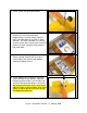
41. Use your radio manual to set up Elevator travel and exponential as shown. Adjust Elevator to get 7/8” (21mm) UP and 5/8” (16mm) DOWN travel. Use 25% expo to soften the center travel per your radio manual. (JR/Spektrum +25% and Futaba/Hitec -25%) *This photo shows the measurement from the elevator neutral position to the full up position. Repeat for full down elevator. 42. Adjust Rudder travel to get 5/16” (10mm) LEFT and 5/16" (10mm) RIGHT. Use 20% expo to soften the center travel per your radio manual.
45. Aileron-Rudder Mix: Setup your computer radio with an Aileron-to-Rudder mix of approx. 25%. This means when you move the Aileron stick to the LEFT (left aileron moves up), the Rudder will also move to the LEFT about 1/4" (6mm). Then move the aileron stick to the full right position (right aileron up) and the Rudder should also move to the right about 1/4” (6mm). We leave ours “ON” all the time. 46.
Preflight If you are new to flying R/C aircraft, or a seasoned modeler, we recommend you have a fellow R/C modeler help you with the first flight. Some items you will need to complete on your first preflight are: 1. Aircraft assembled correctly and ready for flight. 2. All control throws and expos are set per this manual. 3. Transmitter fully charged and on correct model. 4. Aircraft balances at the recommended location. (1-3/4” aft of wing Leading Edge) 5. Flight Battery is fully charged and secure. 6.
2008 Official Academy of Model Aeronautics National Model Aircraft Safety Code GENERAL 1. A model aircraft shall be defined as a non-human-carrying device capable of sustained flight in the atmosphere. It shall not exceed limitations established in this code and is intended to be used exclusively for recreational or competition activity. 2. The maximum takeoff weight of a model aircraft, including fuel, is 55 pounds, except for those flown under the AMA Experimental Aircraft Rules. 3.
7. 8. 9. 10. allocation of frequencies for each site, a day-use agreement between sites, or testing which determines that no interference exists. A frequency-management agreement may exist between two or more AMA chartered clubs, AMA clubs and individual AMA members, or individual AMA members. Frequency-management agreements, including an interference test report if the agreement indicates no interference exists, will be signed by all parties and copies provided to AMA Headquarters.
Hobby Lobby International, Inc. 5614 Franklin Pike Circle Brentwood, TN 37027 1-866-WE-FLY-RC (1-866-933-5972) www.hobby-lobby.com © 2009-2010 Hobby Lobby International, Inc. All rights Reserved. • 5614 Franklin Pike Circle Brentwood, TN 37027 USA www.hobby-lobby.com Pg.20 – Instructions Version 1.