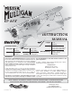
EP ARF INSTRUCTION MANUAL ® Length: SPECIFICATIONS Radio: Wingspan: 52.5 in [1335mm] Weight: 5.25– 5.75 lb [2380– 2610 g] Wing Area: 441 in2 [28.4 dm2] Wing Loading: 27– 30 oz/ft2 [82– 92 g /dm2] Motor/ESC/Prop: 41.5 in [1055mm] 4-5 Channel with 4 micro servos (w/o flaps) or 6 micro servos (with flaps) RimFire™ .32 (42-50-800) ElectriFly SS-45 APC-E 12x8 WARRANTY Great Planes ® Model Manufacturing Co.
TABLE OF CONTENTS AMA INTRODUCTION . . . . . . . . . . . . . . . . . . . . . . . . . . . . . . . .2 AMA . . . . . . . . . . . . . . . . . . . . . . . . . . . . . . . . . . . . . . . . . .2 SAFETY PRECAUTIONS . . . . . . . . . . . . . . . . . . . . . . . . .2 ITEMS REQUIRED. . . . . . . . . . . . . . . . . . . . . . . . . . . . . . .3 Radio Equipment . . . . . . . . . . . . . . . . . . . . . . . . . . . . .3 Motor, ESC, & Propeller Recommendations . . . . . . . .3 Battery & Charger Recommendations . . . .
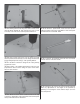
differ slightly from the photos. In those instances the written instructions should be considered as correct. No Flaps Option ❏ (1) Y-harness (FUTM4130) ❏ (4) Futaba 3115 Micro Precision Servo (FUTM0415) OR (4) minimum 39 oz-in (2.8 kg-cm) Micro Servos ❏ 3. You must take time to build straight, true and strong. 4. You must use an R/C radio system that is in good condition, a correctly sized engine, and other components as specified in this instruction manual.
Required Adhesives and Building Supplies IMPORTANT BUILDING NOTES • There are three types of screws used in this kit: Sheet metal screws are designated by a number and a length. For example, #6 x 3/4" [19mm] To finish this airplane you will need the following items. ❏ 1 oz. [30g] Thin Pro™ CA (GPMR6002) ❏ 1 oz. [30g] Medium Pro CA+ (GPMR6008) ❏ 2 oz.
To locate a hobby dealer, visit the Great Planes web site at www.greatplanes.com. Choose “Where to Buy” at the bottom of the menu on the left side of the page. Follow the instructions provided on the page to locate a U.S., Canadian or International dealer. KIT INSPECTION Before starting to build, take an inventory of this kit to make sure it is complete, and inspect the parts to make sure they are of acceptable quality.
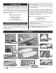
BEFORE YOU BEGIN ❏ ❏ 2. Working with the left wing, remove the aileron servo bay cover. Center the servo arm in the opening with the arm pointing out as shown. With the servo in this position, glue two 7mm x 10mm x 14mm hardwood blocks under the servo mounting tabs. If you are using the recommended Futaba S3115 servos, you may simply use epoxy to glue the blocks in the positions marked inside the cover.
❏ ❏ 5. Tie the guide string to the end of the servo lead and carefully route the servo lead through the wing and out of the hole in the sheeting near the root rib of the wing. ❏ ❏ 8. Clip off and discard the backing plate from a small control horn. Align the horn over the mark you made and slide it forward until the pushrod holes in the horn are directly over the hinge line. Drill two 3/8" [9.5mm] deep holes using a 1/16" [1.6mm] drill. Be careful not to drill completely through the aileron. ❏ ❏ 9.
❏ 16. Glue the 3mm x 20mm wing alignment dowel into the ❏ ❏ 12. Bend the pushrod 90° at the mark that you made. left wing as shown so that at least 10mm is protruding. Fit the pushrod to the servo arm and fasten it with a FasLink pushrod retainer. Cut off the remaining pushrod so that at least 1/4" [6.4mm] of pushrod remains. Fixed Wing Flap (Option 1) ❏ 13. Repeat steps 2 through 12 to prepare the right wing. On this model, you can set up the flaps one of three ways.
6-minute epoxy, you can heat up the glue joint later and easily remove the fixed flap retainers to convert to operable flaps. ❏ 3. Mix up a batch of 6-minute epoxy. Brush epoxy on the leading edge of each flap and the corresponding trailing edge of each wing. Glue each flap in the retracted position. Before the epoxy cures, wipe off the excess with a paper towel dampened with denatured alcohol. ❏ 3. Trim away the covering from the three small holes.
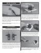
❏ ❏ 5. Working with the left wing first, make a mark on the flap LE directly behind the side opposite the hole in each servo bay cover. This is the side the pushrod will be on. ❏ ❏ 10. Bend the pushrod 90°. Insert the bent portion under the hump of the nylon strap. Make a mark at the point you will make the second 90° bend. ❏ ❏ 6. Hold a small control horn over the mark you made with the pushrod holes directly over the hinge line. Drill two 3/8" [9.5mm] deep holes using a 1/16" [1.6mm] drill bit.
❏ ❏ 2. Establish the rotation direction of your flap servos. ❏ 13. Repeat steps 5 through 12 to finish the right wing. Remember to orient the servo bay cover properly. Use the photo above for reference. Lay one flap servo on its side as shown in the sketch. Turn on your radio and actuate the flap channel. Make sure that the servo rotates in the proper direction in conjunction with the movement of the flap dial or slider. If it doesn’t, reverse the servo operation so that it does. ❏ 14.
❏ ❏ 8. Hold a small control horn over the mark you made with the pushrod holes directly over the hinge line. Drill two 3/8" [9.5mm] deep holes using a 1/16" [1.6mm] drill bit. Be careful not to drill completely through the flap. Install the control horn using two #2x3/8" [9.5mm] sheetmetal screws. Harden the threads in the wood with thin CA. ❏ ❏ 5. Attach a 6" [152mm] servo lead extension to the flap servo. Secure the connection using 3/8" [9.5mm] heat shrink tubing or electrical tape. ❏ ❏ 9.
❏ 2. The main landing gear leg fairings are only slightly different. It is difficult to see the difference by just looking at them. We recommend test fitting both of the landing gear fairings over the main landing gear and checking the fit. If they are properly oriented, they should fit against the fuselage closely. If they do not, try switching them or rotating them front to back. ❏ 12. Repeat steps 1 through 11 for the right wing. ❏ 13. Insert the wing tube into one wing and join the two wings.
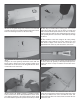
Tail Installation ❏ 5. Grind one 3/16" [4.8mm] wide flat spot at each mark you made. ❏ 1. Cut the protective piece of balsa wood out of the TE of the horizontal stabilizer slot on the fuselage. ❏ 2. Fit the wing to the fuselage using two 1/4-20 nylon wing bolts. ❏ 6. Install the main wheel on the axle using a 5/32" [4mm] wheel collar on either side of the wheel. Use thread locking compound on the 6-32 set screws and tighten the set screws against the flat spots.
remove the tail and lightly sand the bottom of the horizontal stab slot on the high side and the top of the slot on the low side. Re-fit the horizontal and vertical tail and check the alignment once again. Tailwheel and Rudder Installation ❏ 1. Clean the surface of the plastic tailwheel bushing using denatured alcohol. Sand the bent portion of the tailwheel wire. Apply a drop of oil onto the tailwheel wire to prevent the wire from being glued to the bushing. ❏ 5.
❏ 3. Prepare three CA hinges by poking a T-pin through the center of the hinge. ❏ 6. Fit the rudder onto the hinges and the tailwheel wire. Push the rudder forward up against the fin and remove the T-pins. Slide the rudder up or down until the top of the rudder is even with the top of the fin. Deflect the rudder left and right a few times. Hold the rudder to one side and apply 5-7 drops of thin CA to each hinge.
❏ 2. Fit one pushrod into the elevator pushrod guide tube on the left side of the fuselage. ❏ 4. Drill two 3/32" [2.4mm] holes completely through the elevator. ❏ 5. Install the control horn using the backing plate and two 2-56 x 1/2" [12.7mm] machine screws. Fit the clevis to the outermost hole in the control horn. ❏ 6. Clip the excess length of pushrod to allow you to work ❏ 3. Cut the backing plate from the large control horn and set it aside for now.
and a #6 lock nut to secure the screw. Now screw a nylon torque rod horn onto the threaded end of the screw so that it is flush with the end. Connect the clevis. ❏ 7. Drill the servo arm at the second hole outboard using a 5/64 [2mm] drill. Hold the elevators at zero throw and mark where to bend the elevator pushrod. ❏ 11. Prepare a servo. Install the rudder servo the same way you installed the elevator servo. Bend the pushrod 90° and trim the excess pushrod so that at least 1/4" [6.
❏ 6. Cut a 1-1/2" [38mm] piece of adhesive backed hook and loop material. Stick one side to the back of the ESC and the other side to the ESC tray. Clean the back side of your ESC with some denatured alcohol before you stick the hook and loop material onto it. ❏ 3. Mix up some 6-minute epoxy and thin it down with some denatured alcohol. Brush it onto the ESC tray and the battery tray to prepare the wood. Allow the epoxy to cure. ❏ 7. Glue the ESC tray into the fuselage as shown. Fit the ESC.
COWL & PROPELLER INSTALLATION ❏ 9. Test the motor for proper operation. If the motor does not spin in the correct direction, unplug two of the motor wires from the ESC and swap the position of the two wires. Test the motor once again to confirm. Warning: Do not install the propeller until you have performed this check and have determined that the motor works properly. ❏ 1. Cut out the center of the dummy engine to allow access for the prop adapter.
#4 lock washers and four #4 flat washers. Use a 3/32" ball wrench (GPMR8002) to tighten the screws. ❏ 4. Use a sharp hobby knife or small sanding drum to remove the plastic between the dummy engine cylinders. Leave a 20mm wide ring around the edge of the dummy engine. Use sand paper to remove the paint from the lip of the dummy engine. Clean the lip using denatured alcohol. ❏ 5. Sand the inside of the cowl near the rear lip and where the dummy engine will mount.
FINAL ASSEMBLY ❏ 1. Connect the aileron and flap servo leads to the Y-connectors. Install the wing using two 1/4-20 nylon wing bolts. ❏ 2. Identify the two right wing struts. Use the picture above to identify the proper orientation of each strut. ❏ 10. Apply a thin layer of 6-minute epoxy along the inside edge of the cowl. Slide the cowl over the cowl ring and position the cowl so that one of the dummy engine cylinders is straight up and the prop adapter is centered. ❏ 3.
Pilot Installation (Optional) Apply the Decals To install a pilot figure, please use the Great Planes 1/5th scale sport pilot. This is available in red, yellow, or blue. Please see the parts list earlier in this manual for these part numbers. 1. Be certain the model is clean and free from oily fingerprints and dust. Prepare a dishpan or small bucket with a mixture of liquid dish soap and warm water—about one teaspoon of soap per gallon of water.
4-CHANNEL RADIO SET UP (STANDARD MODE 2) RUDDER MOVES RIGHT RIGHT AILERON MOVES UP LEFT AILERON MOVES DOWN ❏ 1. Use a Great Planes AccuThrow™ gauge, a ruler, or an FULL THROTTLE ELEVATOR MOVES DOWN ❏ 3. Make certain that the control surfaces and the throttle respond in the correct direction as shown in the diagram. If any of the controls respond in the wrong direction, use the servo reversing in the transmitter to reverse the servos connected to those controls.
Balance the Model (C.G.) At this stage the model should be in ready-to-fly condition with all of the systems in place including the motor, prop, landing gear, radio system, wheel pants, struts, and battery hatch (canopy). ❏ 2. Strap the battery to the battery tray, but do not connect it. Fit the canopy. Suspend the model upright by placing your fingers on the marks you made. ❏ 3.
PREFLIGHT MOTOR SAFETY PRECAUTIONS Identify Your Model Failure to follow these safety precautions may result in severe injury to yourself and others. No matter if you fly at an AMA sanctioned R/C club site or if you fly somewhere on your own, you should always have your name, address, telephone number and AMA number on or inside your model. It is required at all AMA R/C club flying sites and AMA sanctioned flying events.
Radio Control 1) I will have completed a successful radio equipment ground check before the first flight of a new or repaired model. 2) I will not fly my model aircraft in the presence of spectators until I become a qualified flier, unless assisted by an experienced helper. 3) At all flying sites a straight or curved line(s) must be established in front of which all flying takes place with the other side for spectators.
Takeoff directly into the wind. Gradually advance the throttle while holding a bit of up elevator to keep the tail on the ground to maintain tail wheel steering. Also start applying right rudder. If the throttle is advanced too quickly, the plane will want to turn quickly to the left. As the model gains speed, decrease up elevator allowing the tail to come off the ground.
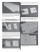
t DOOR TEMPLATE Cu Cut Align these dashed lines with the other windows. Note: Door is only on RH side.
NOTES 30