Agilent Technologies 87050A Option H15 User’s and Service Guide
Agilent Technologies 87050A Option H15 Multiport Test Set User’s and Service Guide Agilent Technologies Part Number: 87050-90029 Printed in USA October 2000
Notices No part of this manual may be reproduced in any form or by any means (including electronic storage and retrieval or translation into a foreign language) without prior agreement and written consent from Agilent Technologies, Inc. as governed by United States and international copyright laws. Restricted Rights Legend Use, duplication, or disclosure by the U.S.
Contents 1. Agilent Technologies 87050A Option H15 Introduction . . . . . . . . . . . . . . . . . . . . . . . . . . . . . . . . . . . . . . . . . . . . . Installing the Test Set . . . . . . . . . . . . . . . . . . . . . . . . . . . . . . . . . . . . . Step 1. Check the Shipment. . . . . . . . . . . . . . . . . . . . . . . . . . . . . . . Step 2. Meet Electrical and Environmental Requirements . . . . . . 1-2 1-3 1-3 1-4 2. Getting Started Getting Started . . . . . . . . . . . . . . . . . . . . . . . . . .
5. Controlling the Test Set and Making Measurements Introduction . . . . . . . . . . . . . . . . . . . . . . . . . . . . . . . . . . . . . . . . . . . . . 5-2 Commands . . . . . . . . . . . . . . . . . . . . . . . . . . . . . . . . . . . . . . . . . . . . . . 5-3 Computer Control . . . . . . . . . . . . . . . . . . . . . . . . . . . . . . . . . . . . . . . 5-3 Network Analyzer Control . . . . . . . . . . . . . . . . . . . . . . . . . . . . . . 5-5 Calibrating the Test System . . . . . . . . . . . . . . . .
Contents 7. Safety and Regulatory Information Safety and Regulatory Information . . . . . . . . . . . . . . . . . . . . . . . . . . Introduction . . . . . . . . . . . . . . . . . . . . . . . . . . . . . . . . . . . . . . . . . . . Safety Information . . . . . . . . . . . . . . . . . . . . . . . . . . . . . . . . . . . . . . Warnings . . . . . . . . . . . . . . . . . . . . . . . . . . . . . . . . . . . . . . . . . . . . Cautions . . . . . . . . . . . . . . . . . . . . . . . . . . . . . . . . . . . . . . . .
Contents-4
1 Agilent Technologies 87050A Option H15 User’s and Service Guide 1-1
Agilent Technologies 87050A Option H15 Introduction Introduction The Agilent 87050A Option H15 multiport test set is designed for use with Agilent Technologies 50 Ω network analyzers such as the Agilent 871x series, Agilent 8753D, and Agilent 8753E. The test set provides the ability to make single connection, multiple measurements of multiport devices with up to 16 ports, such as distribution amplifiers, taps, switches, and couplers.
Agilent Technologies 87050A Option H15 Installing the Test Set Installing the Test Set This chapter will guide you through the steps necessary to correctly and safely install your multiport test set. The steps are: 1. Check the Shipment. 2. Meet Electrical and Environmental Requirements. Step 1. Check the Shipment 1. After you have unpacked your test set, you should keep the original packaging materials so they can be used if you need to transport the instrument. 2.
Agilent Technologies 87050A Option H15 Installing the Test Set Step 2. Meet Electrical and Environmental Requirements 1. The line power module on your test set is an autoranging input. It is designed to be used with an ac power source with a nominal voltage of either 115 V or 230 V. 2. Ensure that the available ac power source meets the following requirements: 90 to 250 Vac, 48 to 66 Hz, 40 W CAUTION This product has an autoranging line voltage input.
Agilent Technologies 87050A Option H15 Installing the Test Set 4. Verify that the power cable is not damaged, and that the power source outlet provides a protective earth-ground contact. Note that the following illustration depicts only one type of power source outlet. Refer to Figure 3-3 on page 3-6 to see the different types of power cord plugs that can be used with your test set.
Agilent Technologies 87050A Option H15 Installing the Test Set 5. Ensure that there are at least two inches of clearance around the sides and back of the test set and the system cabinet (if used). Refer to Figure 1-2. Figure 1-2 CAUTION Ventilation Clearance Requirements Ventilation Requirements: When installing the instrument in a cabinet, the convection into and out of the instrument must not be restricted.
Agilent Technologies 87050A Option H15 Installing the Test Set 6. Set up a static safe workstation. Electrostatic discharge (ESD) can damage or destroy components.
Agilent Technologies 87050A Option H15 Installing the Test Set 1-8 User’s and Service Guide
2 Getting Started User’s and Service Guide 2-1
Getting Started Getting Started Getting Started Connecting and Turning on the Test Set The test set is designed to be placed underneath the network analyzer in a rack system and connected to it as shown in Figure 2-1 (if you are using a standard Agilent 8753D/E) or Figure 2-2 on page 2-3 (if you are using an Agilent 8753D/E Option 011 specifically).
Getting Started Getting Started Figure 2-2 Connecting the Test Set to the Agilent 8753D Option 011 Network Analyzer AGILENT 8753D OPTION 011 NETWORK ANALYZER WITH AGILENT 85047A S-PARAMETER TEST SET PORT 1 WITH APC-7 TO TYPE-N (F) ADAPTER (P/N 85054-60001) PORT 2 WITH APC-7 TO TYPE-N (F) ADAPTER (P/N 85054-60001) REFLECTION TRANSMISSION AGILENT 87050A OPTION H15 After all the proper connections have been made, turn on the test set using the front panel line switch.
Getting Started Getting Started Figure 2-3 The Test Set Address Switch 2-4 User’s and Service Guide
Getting Started Getting Started Performing the Operator’s Check For information on how to control the test set, refer to Chapter 5, “Controlling the Test Set and Making Measurements,” on page 5-1. Description The following operator’s check is designed to provide you with a high degree of confidence that your test set is working properly. It is not designed to verify specifications. To verify specifications, refer to Chapter 4, “Specifications,” on page 4-1 in this manual.
Getting Started Getting Started 2-6 User’s and Service Guide
3 The Front and Rear Panels This chapter contains information about the ports and switches found on the front and rear panels of the test set. This chapter is divided into two sections: front panel and rear panel.
The Front and Rear Panels Front Panel Front Panel Figure 3-1 Front Panel Reflection (Type-N) Transmission (Type-N) Ports 1 - 16 (SMA) Line Power Switch Port Connection Status Ground Connector Line Power Switch The test set line power switch is located at the bottom left corner of the front panel. See Figure 3-1. The line power switch turns the power to the test set either on or off.
The Front and Rear Panels Front Panel The Transmission and Reflection Ports The transmission and reflection ports are 50 Ω type-N connectors. A 50 Ω cable connects directly to the Reflection/Transmission port or Port 1/Port 2 of the network analyzer by means of the cables (Agilent part number 8120-6995) and adapters (Agilent part number 85054-60001) that were shipped with your test set. CAUTION Check your analyzer documentation for power levels above which the ports can be damaged.
The Front and Rear Panels Rear Panel Rear Panel Figure 3-2 Rear Panel Parallel Port Input Parallel Port Output Printer Test Set Switch GPIB Connector Address Switch Line Module The Parallel Port Input Connector This input is connected to the network analyzer. The analyzer provides control signals that drive the switches inside the test set. In pass-through mode, it also accepts signals required to drive a printer.
The Front and Rear Panels Rear Panel GPIB (HP-IB) Connector This connector allows the test set to be connected directly to a controller that uses GPIB (HP-IB) commands. Refer to “Controlling the Test Set,” Figure 5-3 on page 5-11. Address Switch The address switch sets either the GPIB (HP-IB) or the parallel address of the test set. See “Setting the Test Set Address Switch” on page 2-3 for information. Line Module The line module contains the power cable receptacle and the line fuse.
The Front and Rear Panels Rear Panel Figure 3-3 Power Cable and Line (Mains) Plug Part Number a Plug Type 250V Cable Part Number Plug b Length Description cm (in.
The Front and Rear Panels Rear Panel Fuses The line fuse and a spare reside within the line module. Figure 3-4 illustrates where the fuses are and how to access them. Available Fuses United States (115 V orientation) • Fuse (F 3 A/250 V, Agilent part number 2110-0780), U.L. listed and CSA certified. Europe (230 V orientation) • Fuse (F 3.15 A/250 V, Agilent part number 2110-0655), IEC certified and U.L. recognized.
The Front and Rear Panels Rear Panel 3-8 User’s and Service Guide
4 Specifications User’s and Service Guide 4-1
Specifications Specifications Specifications Table 4-1 Agilent 87050A Option H15 Specifications Parameter Frequency Range Specification 300 kHz to 6.0 GHz Insertion Loss 300 kHz up to 1.3 GHz ≤1.5 dB 1.3 GHz up to 3.0 GHz ≤1.75 dB 3.0 GHz to 6.0 GHz ≤2.5 dB Return Loss (Switch Path ON) 300 kHz up to 1.3 GHz ≥25 dB 1.3 GHz up to 3.0 GHz ≥16 dB 3.0 GHz to 6.0 GHz ≥12 dB Return Loss (Switch Path OFF) 300 kHz up to 1.3 GHz ≥26 dB (typical) 1.3 GHz up to 3.0 GHz ≥21 dB (typical) 3.0 GHz to 6.
Specifications Specifications General Characteristics Table 4-2 Environmental Characteristics General Conditions ESD (electrostatic discharge) must be eliminated by means of static-safe work procedures and an antistatic workstation such as that illustrated in Figure 1-3 on page 1-7 Operating Environment (for indoor use only) Altitude up to 15,000 feet (4,572 meters) Operating Temperature 0° C to 55° C Maximum Relative Humidity 80% for temperatures up to 31° C, decreasing linearly to 50% relative hum
Specifications Specifications 4-4 User’s and Service Guide
5 Controlling the Test Set and Making Measurements User’s and Service Guide 5-1
Controlling the Test Set and Making Measurements Introduction Introduction The Agilent 87050A Option H15 is a “slave” instrument: a controller must be used to control the test set. There are three ways in which the test set can be controlled: 1. The controller can communicate to the network analyzer using GPIB (HP-IB) commands, which then controls the test set by the parallel connection. 2. The controller can control the test set directly by GPIB (HP-IB) commands. 3.
Controlling the Test Set and Making Measurements Commands Commands These three methods of control and their commands are detailed below and on the following pages. Computer Control The first method of controlling the test set is to write GPIB (HP-IB) commands to the network analyzer, which then writes the command to the test set by way of the parallel port. The following examples use the variable D, which is defined in Table 5-1 on page 5-6.
Controlling the Test Set and Making Measurements Commands Figure 5-1 Controlling the Test Set Over GPIB (HP-IB) AGILENT 8753E NETWORK ANALYZER GPIB CONTROLLER AGILENT 87050A OPTION H15 NOTE It is not necessary to have the test set connected to the network analyzer when you are controlling the test set over GPIB (HP-IB).
Controlling the Test Set and Making Measurements Commands Network Analyzer Control The third method of sending commands uses the network analyzer to control the test set directly. This method is performed with the standard setup of the network analyzer working with the test set. A parallel cable is connected from the network analyzer parallel output to the test set parallel input on the rear panels of both instruments. NOTE The following key conventions are used throughout this document.
Controlling the Test Set and Making Measurements Commands Table 5-1 Test Port Addresses Connection Path Decimal [D] Binary Equivalent GPIB (HP-IB) Command Reflection to Port 1 0 00000000 refl_01 Reflection to Port 2 1 00000001 refl_02 Reflection to Port 3 2 00000010 refl_03 Reflection to Port 4 3 00000011 refl_04 Reflection to Port 5 4 00000100 refl_05 Reflection to Port 6 5 00000101 refl_06 Reflection to Port 7 6 00000110 refl_07 Reflection to Port 8 7 00000111 refl_08
Controlling the Test Set and Making Measurements Commands To connect all ports to their internal 50 Ω loads, send the following command: OUTPUT 712;"*all_term;" NOTE When a test set port is not in use, it is terminated in 50 Ω.
Controlling the Test Set and Making Measurements Commands Table 5-2 Switch Number GPIB Command Switch Number GPIB (HP-IB) Command S10 SW10? S11 SW11? S12 SW12? S14 SW14? S15 SW15? S16 SW16? S18 SW18? S19 SW19? S51 SW51? S53 SW53? S55 SW55? S57 SW57? S62 SW62? S63 SW63? S64 SW64? S65 SW65? S66 SW66? S67 SW67? S68 SW68? S69 SW69? S70 SW70? S71 SW71? S72 SW72? S74 SW74? To enter commands for activating each switch port individually, use the switch-port identi
Controlling the Test Set and Making Measurements Commands Calibrating the Test System After the test set has warmed up for at least two hours, you should calibrate it before making any measurements. Refer to your network analyzer user’s guide to determine the type of calibration appropriate for the measurements you will be making. You will need to calibrate each measurement path separately and store the calibration as an instrument state in the network analyzer.
Controlling the Test Set and Making Measurements Commands Making Measurements The following examples assume that you are using a parallel port connection with an Agilent 8753D/E, with the test set parallel address set to 0. Refer to “Setting the Test Set Address Switch” on page 2-3, for information on setting the test set address. Measuring Transmission Refer to Figure 5-3 on page 5-11 for the following discussion.
Controlling the Test Set and Making Measurements Commands Figure 5-3 Controlling the Test Set AGILENT 8753E NETWORK ANALYZER PARALLEL PORT GPIB CONTROLLER AGILENT 87050A OPTION H15 PARALLEL PORT INPUT DUT IN OUT Measuring Reflection By leaving the DUT connected as in Figure 5-3, and setting the network analyzer to measure S11, you can measure reflection or return loss. Example Program An example program for making measurements is briefly described and listed on the following pages.
Controlling the Test Set and Making Measurements Commands The Control Program The Control program demonstrates the control of the Agilent 87050A Option H15 by GPIB (HP-IB) commands or the parallel port. This program can be used to select any port combination manually (listed on the following pages). This program will first ask the user which method will be used to control the Agilent 87050A Option H15, either GPIB (HP-IB) or parallel port. It will then ask which ports are to be enabled.
Controlling the Test Set and Making Measurements Commands 180 ! 190 ! 200 ! 210 Nwa_addr=716 220 Ts_addr=712 230 ! 240 CLEAR SCREEN 250 PRINT USING "3/,K,/";"***** FOR Agilent 87050A-H15 260 PRINT "Either direct GPIB control of the Agilent 87050A-H15 may be selected (h)," 270 PRINT "or indirect control via the Parallel Port (p) of the Agilent 8753D,E" 280 REPEAT Developed at Microwave Instruments Division Santa Rosa, CA Revision A.01.
Controlling the Test Set and Making Measurements Commands 470 ! 480 PRINT USING "/,K,/";RPT$("-",77) 490 PRINT "For manual operation of this switch box, enter TWO numbers separated by" 500 PRINT "a comma (,). The two numbers represent the port numbers directed to the" 510 PRINT "Reflection Port and Transmission Port, respectively. Setting a port to" 520 PRINT "'0' will terminate the corresponding port." 530 PRINT "Unless both numbers are '0', the two values cannot be the same.
Controlling the Test Set and Making Measurements Commands 720 LOOP 730 Refl=0 740 Trans=0 750 BEEP 500,.1 760 LINPUT "Enterthe Reflection Port/Transmission Port selections separated by commas: e.g.
Controlling the Test Set and Making Measurements Commands 1020 DISP "Port selections MUST be different if non-zero; Range= 0 to 16. Entered """&Current$&","&Command$&"""" 1030 BEEP 1500,.
Controlling the Test Set and Making Measurements Commands 1320 1330 1340 1350 PRINT TABXY(1,29)," PRINT TABXY(1,28),"All ports are terminated into 50 ohms.
Controlling the Test Set and Making Measurements Commands 1580 WAIT 3 1590 END SELECT 1600 ELSE 1610 DISP "Unknown command """;Command$;"""" 1620 BEEP 300,.1 1630 WAIT 3 1640 END IF 1650 END SELECT 1660 END IF 1670 END LOOP 1680 END 1690 ! 1700 SUB Set_switches(Addr,First_parm$,Second_parm$, Contr oller$) 1710 !==================================================== 1720 ! PURPOSE:To set the Agilent 87050A Option H15 switches.
Controlling the Test Set and Making Measurements Commands 1890 !==================================================== 1900 Set_switches: 1910 ! ! 1920 SELECT UPC$(TRIM$(First_parm$)) 1930 CASE "REFL" 1940 SELECT UPC$(TRIM$(Second_parm$)) 1950 CASE "0","TERMINATE REFLECTION" 1960 Hswitch_code$="*r_term" 1970 Pswitch_code$="16" 1980 CASE "1","PORT 1 TO REFLECTION" 1990 Hswitch_code$="refl_01" 2000 Pswitch_code$="0" 2010 CASE "2","PORT 2 TO REFLECTION" 2020 Hswitch_code$="refl_02" 203
Controlling the Test Set and Making Measurements Commands 2230 Hswitch_code$="refl_09" 2240 Pswitch_code$="8" 2250 CASE "10","PORT 10 TO REFLECTION" 2251 Hswitch_code$="refl_10" 2252 Pswitch_code$="9" 2255 CASE "11","PORT 11 TO REFLECTION" 2256 Hswitch_code$="refl_11" 2257 Pswitch_code$="10" 2260 CASE "12","PORT 12 TO REFLECTION" 2262 Hswitch_code$="refl_12" 2263 Pswitch_code$="11" 2265 CASE "13","PORT 13 TO REFLECTION" 2267 Hswitch_code$="refl_13" 2268 Pswitch_code$="12" 2270 C
Controlling the Test Set and Making Measurements Commands 2296 2297 Pswitch_code$="33" CASE "1","PORT 1 TO TRANSMISSION" 2298 Hswitch_code$="tran_01" 2299 Pswitch_code$="17" 2300 CASE "2","PORT 2 TO TRANSMISSION" 2301 Hswitch_code$="tran_02" 2302 Pswitch_code$="18" 2303 CASE "3","PORT 3 TO TRANSMISSION" 2304 Hswitch_code$="tran_03" 2305 Pswitch_code$="19" 2306 CASE "4","PORT 4 TO TRANSMISSION" 2307 Hswitch_code$="tran_04" 2308 Pswitch_code$="20" 2309 CASE "5","PORT 5 TO TRANSMISSION
Controlling the Test Set and Making Measurements Commands 2330 CASE "12","PORT 12 TO TRANSMISSION" 2331 Hswitch_code$="tran_12" 2332 Pswitch_code$="28" 2333 CASE "13","PORT 13 TO TRANSMISSION" 2334 Hswitch_code$="tran_13" 2335 Pswitch_code$="29" 2336 CASE "14","PORT 14 TO TRANSMISSION" 2337 Hswitch_code$="tran_14" 2338 Pswitch_code$="30" 2339 CASE "15","PORT 15 TO TRANSMISSION" 2340 Hswitch_code$="tran_15" 2341 Pswitch_code$="31" 2342 CASE "16","PORT 16 TO TRANSMISSION" 2343 Hswit
6 Servicing the Test Set This chapter contains information about the following: • performance testing • performance test record • replaceable parts • troubleshooting the test set • theory of operation CAUTION Read all applicable safety warnings and cautions in Chapter 7, “Safety and Regulatory Information,” on page 7-1, before servicing the test set.
Servicing the Test Set Performance Testing Performance Testing Performance testing consists of measuring insertion loss, return loss, and isolation between all ports. NOTE For the most accurate measurements, the use of an Agilent 8753D/E 50 Ω network analyzer is recommended and its use is assumed in these testing instructions. Familiarity with RF and microwave measurements is also assumed. The use of adapters may be required and their effects should be accounted for.
Servicing the Test Set Performance Testing There are no adjustments required for the Agilent 87050A Option H15 test set. Set up the network analyzer using the following procedure. Step 1. Set the number of points to 401 by pressing: [MENU] > NUMBER OF POINTS > [401] Step 2. Set the IF Bandwidth to 10 Hz by pressing: [AVG] > IF > BW > [10] > [x1] Step 3. Connect the test port cables to Port 1 and Port 2 on the network analyzer. Step 4.
Servicing the Test Set Performance Testing Adapter Delay Removal Step 1. Perform an S11 calibration on Port 1 of the network analyzer. Step 2. Connect the 3.5 mm end of the 3.5 mm to APC-7 adapter, Agilent part number 1250-1747, directly to Port 1 of the network analyzer. Step 3. Connect a 7 mm short to the APC-7 side of the connector Step 4. Set the analyzer to polar format by pressing: [FORMAT] > POLAR Step 5. Press: [CAL] > MORE > PORT EXTENSIONS > EXTENSIONS ON > EXTENSIONS INPUT 1 Step 6.
Servicing the Test Set Performance Testing Calibration Step 1. Connect two (2) 3.5 mm flexible test port cables to Port 1 and Port 2 of the network analyzer. Step 2. Connect the APC-7 to 3.5 mm adapter to the end of the test Port 2 cable. Step 3. Perform the first full two-port calibration using a 3.5 mm calibration kit. Use the 3.5 mm standards. Step 4. When the isolation calibration is performed, set the averaging to 16. Step 5. Save the calibration to the internal disk and label it "Cal1". Step 6.
Servicing the Test Set Performance Testing Testing for Insertion Loss Step 1. Recall the adapter removal calibration from the analyzer internal disk by pressing: [SAVE/RECALL] > SAVE STATE Step 2. Connect the cable attached to Port 1 of the network analyzer to the Transmission port of the test set. Step 3. Connect the cable from Port 2 of the network analyzer to Port 1 of the test set. Step 4.
Servicing the Test Set Performance Testing Testing for Isolation Isolation needs to be measured only on adjacent ports. Two 50 Ω loads are required for this test. Step 1. Recall the adapter removal calibration stored previously in the internal memory of the network analyzer Step 2. Connect two (2) high-quality 50 Ω loads to both the Transmission and Reflection ports on the test set. Step 3. Turn the averaging on by pressing: [AVG] > AVERAGING ON Step 4.
Servicing the Test Set Performance Testing Testing for Return Loss This test will check both the internal termination load of each port, as well as the through match when the appropriate input port is terminated with a 50 Ω load. Set up the network analyzer using the following procedure. Step 1. Set the number of points to 401 by pressing: [MENU] > NUMBER OF POINTS > [401] Step 2. Set the IF Bandwidth to 10 Hz by pressing: [AVG] > IF BW > [10] > [x1] Step 3.
Servicing the Test Set Performance Testing Step 13. Using the front panel knob, locate the maximum value of the data trace for the 50 MHz to 2.0 GHz frequency range. Step 14. Write the maximum value in the “Return Loss Test Record”, Table 6-3 on page 6-14, for the port being measured. Step 15. Repeat the previous two steps for the other frequency ranges listed in the “Return Loss Test Record”. Step 16. Press: [SEQ] > TTL I/O > PARALLEL OUT ALL > [34] > [x1] Step 17.
Servicing the Test Set Performance Test Record Performance Test Record NOTE This page and the following pages (Performance Test Record) are designed to be duplicated and used as a template for either of the Transmission or Reflection ports during each of the performance tests (Insertion Loss, Return Loss, and Isolation). At the top of each page, circle the appropriate input port, Transmission or Reflection, and write in the test date.
Servicing the Test Set Performance Test Record Transmission/Reflection Table 6-1 Date___________ Agilent 87050A Option H15 Insertion Loss Test Record (1 of 2) Test Description Port Specification (dB) Measured Results Measurement Uncertainty (dB) (dB) Insertion Loss 1 ≤1.5 __________ ±0.3 300 kHz up to 1.3 GHz 2 ≤1.5 __________ ±0.3 3 ≤1.5 __________ ±0.3 4 ≤1.5 __________ ±0.3 5 ≤1.5 __________ ±0.3 6 ≤1.5 __________ ±0.3 7 ≤1.5 __________ ±0.3 8 ≤1.
Servicing the Test Set Performance Test Record Transmission/Reflection Table 6-1 Date___________ Agilent 87050A Option H15 Insertion Loss Test Record (2 of 2) Test Description Port Specification (dB) Measured Results (dB) Measurement Uncertainty (dB) Insertion Loss 1 ≤2.5 __________ ±0.3 3.0 GHz to 6.0 GHz 2 ≤2.5 __________ ±0.3 3 ≤2.5 __________ ±0.3 4 ≤2.5 __________ ±0.3 5 ≤2.5 __________ ±0.3 6 ≤2.5 __________ ±0.3 7 ≤2.5 __________ ±0.3 8 ≤2.5 __________ ±0.
Servicing the Test Set Performance Test Record Transmission/Reflection Table 6-2 Date___________ Agilent 87050A Option H15 Isolation Test Record (1 of 1) Test Description Port Specification Measured Results (dB) (dB) Measurement Uncertainty (dB) Isolation 1 ≥100 __________ ±5 300 kHz up to 3.
Servicing the Test Set Performance Test Record Transmission/Reflection Table 6-3 Date___________ Agilent 87050A Option H15 Return Loss Test Record (1 of 3) Test Description Port Specification (dB) Measured Results Measurement Uncertainty (dB) (dB) Return Loss 1 ≥25 __________ ±1.5 300 kHz up to 1.3 GHz 2 ≥25 __________ ±1.5 Switch Path ON 3 ≥25 __________ ±1.5 4 ≥25 __________ ±1.5 5 ≥25 __________ ±1.5 6 ≥25 __________ ±1.5 7 ≥25 __________ ±1.
Servicing the Test Set Performance Test Record Transmission/Reflection Table 6-3 Date___________ Agilent 87050A Option H15 Return Loss Test Record (2 of 3) Test Description Port Specification (dB) Measured Results (dB) Measurement Uncertainty (dB) Return Loss 1 ≥12 __________ ±0.6 3.0 GHz up to 6.0 GHz 2 ≥12 __________ ±0.6 Switch Path ON 3 ≥12 __________ ±0.6 4 ≥12 __________ ±0.6 5 ≥12 __________ ±0.6 6 ≥12 __________ ±0.6 7 ≥12 __________ ±0.
Servicing the Test Set Performance Test Record Transmission/Reflection Table 6-3 Date___________ Agilent 87050A Option H15 Return Loss Test Record (3 of 3) Test Description Port Specification 1 2 3 4 5 6 7 8 9 10 11 12 13 14 15 16 ≥21 ≥21 ≥21 ≥21 ≥21 ≥21 ≥21 ≥21 ≥21 ≥21 ≥21 ≥21 ≥21 ≥21 ≥21 ≥21 __________ __________ __________ __________ __________ __________ __________ __________ __________ __________ __________ __________ __________ __________ __________ __________ Measurement Uncertainty (dB) ±
Servicing the Test Set Replaceable Parts Replaceable Parts Table 6-4 Replaceable Parts Replacement Part Agilent Part Number Quantity Power Supply, 110 W 0950-2252 1 Adapter, 3.
Servicing the Test Set Replaceable Parts Table 6-4 Replaceable Parts Replacement Part Agilent Part Number Quantity RF Cable, J15-6 to J51-1, J16-6 to J57-1* 87050-20079 2 RF Cable, J14-5 to J51-1* 87050-20080 1 RF Cable, J15-6 to J53-1* 87050-20081 1 RF Cable, J15-5 to J62-1, J16-5 to J68-1* 87050-20082 2 RF Cable, J15-2 to J64-1, J16-2 to J70-1* 87050-20083 2 RF Cable, J14-3 to J66-1* 87050-20084 1 RF Cable, J15-4 to J63-1, J16-4 to J69-1* 87050-20085 2 RF Cable, J15-3 to J65-1, J
Servicing the Test Set Replaceable Parts Table 6-4 Replaceable Parts Replacement Part Agilent Part Number Quantity RF Cable, J70-C to Port 14* 87050-20171 1 RF Cable, J73-C to Port 15* 87050-20172 1 RF Cable, J72-C to Port 16* 87050-20173 1 RF Cable, J10-2 to J70-2* 87050-20174 1 RF Cable, J12-1 to J71-2* 87050-20175 1 RF Cable, J14-1 to J72-1* 87050-20176 1 RF Cable, J15-1 to J73-1* 87050-20177 1 RF Cable, J11-3 to J72-2* 87050-20178 1 RF Cable, J10-1 to J73-2* 87050-20179 1
Servicing the Test Set Troubleshooting the Test Set Troubleshooting the Test Set This section contains information on troubleshooting the test set to the assembly level only. By following these procedures you should be able to determine whether the power supply, front panel, or main switch board needs replacing. A block diagram is included at the end of this section as an aid in troubleshooting. Theory of operation information can be found in the next section of this manual.
Servicing the Test Set Troubleshooting the Test Set Troubleshooting the Front Panel Board Turn the instrument power on and do the following: Step 1. Check the condition of each of the switching paths by issuing commands to switch each of the paths to either the Transmission or Reflection path. Ensure that the LCD indicates the appropriate path. Step 2. If the LCD indicates a wrong path, the problem can lie with either the front panel board or the main switch board.
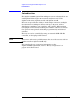
6-22 2 3 4 C 5 5 6 3 2 Reflection J70-2 J63-2 J51-2 J62-2 J74-2 J53-2 1 6 J18 2 3 4 C 5 6 NC 1 J11 NC 2 4 C 5 6 J69-2 J57-2 J72-2 J68-2 3 A2 Display LCD Board 2 3 1 1 J63 2 1 2 J62 2 1 3 J51 2 1 4 J65 2 1 J64 5 2 1 6 J53 2 1 7 J67 2 1 2 1 9 J55 2 1 2 10 J69 Test Ports 8 J66 4 C 5 6 6 J19 5 2 2 3 4 C 5 50==Ω 1 2 11 J68 1 2 12 J57 1 2 13 J71 6 J55-1 J67-1 NC J72-1 J66-1 J53-1 1 J14 3 2 14 J70 1 2 15 J74
Servicing the Test Set Theory of Operation Theory of Operation The theory of operation begins with a general description of the Agilent 87050A Option H15 multiport test set. This is followed by more detailed operating theory. The operation of each group is described briefly, to the assembly level only. Detailed component level circuit theory is not provided.
Servicing the Test Set Theory of Operation A3 Controller Board (Mother Board) and Switch Driver Board (Daughter Board) Theory Refer to the block diagram, Figure 6-1 on page 6-22, for the following discussion. The mother and daughter boards provide the bias for the switching paths for the various ports to the Transmission and Reflection ports. The front panel display contains an LCD that indicates the switched ports. A particular test port (1 through 16) can be in one of three states.
7 Safety and Regulatory Information User’s and Service Guide 7-1
Safety and Regulatory Information Safety and Regulatory Information Safety and Regulatory Information Introduction Review this product and related documentation to familiarize yourself with safety markings and instructions before you operate the instrument. This product has been designed and tested in accordance with international standards. Cleaning Instructions Clean the instrument cabinet using a damp cloth only.
Safety and Regulatory Information Safety and Regulatory Information Safety Information Warnings WARNING The WARNING notice denotes a hazard. It calls attention to a procedure, practice, or the like, which if not correctly performed or adhered to, could result in personal injury. Do not proceed beyond a WARNING notice until the indicated conditions are fully understood and met. Warnings applicable to this instrument are: WARNING No operator serviceable parts inside.
Safety and Regulatory Information Safety and Regulatory Information Cautions CAUTION The CAUTION notice denotes a hazard. It calls attention to an operating procedure, practice, or the like, which if not correctly performed or adhered to, could result in damage to the product or loss of important data. Do not proceed beyond a CAUTION notice until the indicated conditions are fully understood and met.
Safety and Regulatory Information Safety and Regulatory Information Instrument Markings ! When you see this symbol on your instrument, you should refer to the instrument’s instruction manual for important information. This symbol indicates hazardous voltages. The laser radiation symbol is marked on products that have a laser output. This symbol indicates that the instrument requires alternating current (ac) input. The CE mark is a registered trademark of the European Community.
Safety and Regulatory Information Agilent Technologies Sales and Service Offices Agilent Technologies Sales and Service Offices UNITED STATES Instrument Support Center Agilent Technologies (800) 403-0801 EUROPEAN FIELD OPERATIONS Headquarters Agilent Technologies S.A. 150, Route du Nant-d’Avril 1217 Meyrin 2/ Geneva Switzerland (41 22) 780.