DATA CENTER SOLUTIONS For More Information: (866) 787-3271 Sales@PTSdcs.
American Power Conversion Legal Disclaimer The information presented in this manual is not warranted by the American Power Conversion Corporation to be authoritative, error free, or complete. This publication is not meant to be a substitute for a detailed operational and site specific development plan.
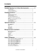
Contents Overview .......................................................................... 1 Scalable Solution for Critical Environments ................ 2 InRow Advantages . . . . . . . . . . . . . . . . . . . . . . . . . . . . . . . . . . . . . . . . . . . . . . . . . . . . . . . . . . 2 Scalable for High Density . . . . . . . . . . . . . . . . . . . . . . . . . . . . . . . . . . . . . . . . . . . . . . . . . . . . 2 Hot Aisle Containment System . . . . . . . . . . . . . . . . . . . . . . . . . . . . .
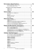
Performance Specifications ......................................... 19 Net Cooling Capacity (Air and Glycol Cooled) . . . . . . . . . . . . . . . . . . . . . . . . . . . . . . . . . . . 19 Net Cooling Capacity (Water Cooled) . . . . . . . . . . . . . . . . . . . . . . . . . . . . . . . . . . . . . . . . . . 20 Performance at Percentage of Fan Speed . . . . . . . . . . . . . . . . . . . . 21 ACRD100 Series . . . . . . . . . . . . . . . . . . . . . . . . . . . . . . . . . . . . . . . . . . . . . . . . . . .
Guide Specifications ..................................................... 43 Guidelines for Installation . . . . . . . . . . . . . . . . . . . . . . . . . . . . . . . . .48 Room preparation . . . . . . . . . . . . . . . . . . . . . . . . . . . . . . . . . . . . . . . . . . . . . . . . . . . . . . . . . . 48 Service access . . . . . . . . . . . . . . . . . . . . . . . . . . . . . . . . . . . . . . . . . . . . . . . . . . . . . . . . . . . . 48 Receiving the unit . . . . . . . . . . . . . . . . . . . . . . .
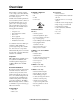
Overview The modular, row-based computer room cooling system offers efficient, predictable, and economical cooling for a variety of spaces. Critical environmental requirements now reach far beyond the confines of the traditional data center or computer room to encompass a larger suite of applications, referred to as technology rooms.
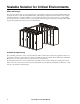
Scalable Solution for Critical Environments InRow Advantages The row-based solution improves energy efficiency and cooling ability in a number of ways. First, the InRow RD draws air directly from the hot aisle, allowing the InRow RD to take advantage of higher heat transfer efficiency due to higher temperature differences. It can then discharge room-temperature air directly in front of the servers it is cooling.
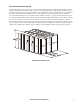
Hot Aisle Containment System Modular ceiling tiles and doors can be used to enclose the hot aisle. This increases the densities that can be handled in a single rack enclosure by eliminating mixing of hot and cold air streams. This method, called load neutralization, removes the heat from the hot aisle, cools it, and then returns it to the surrounding room area at or slightly below room temperature.
Standard Features Cabinet Counterflow Cooling Coil/ Condensate Pan Condensate Pump ACRD100 and ACRD200 series: The frame is constructed of 16 gauge formed steel for maximum strength. The cabinet is serviceable from the front and rear. All exterior panels and corner posts on the frame are powder coated for durability and an attractive finish. The front and rear exterior panels are constructed of 18 gauge perforated steel with 69.5% open free area.
Optional Features Cable Water Detector Filters Data Partition A leak detection cable is placed on the floor or subfloor around all possible leak sources. If water or other conductive liquids contact the cable anywhere along its length, the microprocessor controller announces the leak visually, audibly, and across the network. The 6.1-m (20-ft) cable may be cascaded to make custom lengths up to 24.4 m (80 ft).
Microprocessor Controller Status Check Log Critical Alarm LED ESC Warning Alarm LED ? Check Log LED Status LED Liquid Crystal Display (LCD) Menu Selection scroll keys Escape key Enter key Help key Warning Critical Microprocessor Controller Control Type Logging The microprocessor controller is standard on each unit.
Alarms The microprocessor controller shall activate a visible and audible alarm in the following occurrences: All series: • Cool Fail ACRD100 series and ACRD200 series only: • Condensate pan full • Compressor drive communication fault • Upper fan power supply fault • Compressor drive fault • Lower fan power supply fault • Compressor drive warning • Suction temperature sensor failure • Compressor run hours violation • Persistent low suction pressure fault • Condensate pump run hours violation • Ai
InRow RD Models na2625a Exterior components: ACRD100 and ACRD200 series 8 Removable rear door Adjustable leveling feet Side panel latch Display interface Removable side panel Removable front door Rear casters (non-swiveling) Door lock (front and rear) Front casters (swiveling) InRow RD Technical Data Manual
na2626a Interior components (front): ACRD100 series Electrical control box 1 (retractable) Compressor Electrical control box 2 Front air block panel Return air temperature sensor Evaporator fans (6 total) Condensate pan floats (2 total) Expansion valve Condensate pan Evaporator coil InRow RD Technical Data Manual 9
na2627a Interior components (rear): ACRD100 series 10 Filter/dryer Hot gas bypass valve Pressure transducer (2 total, located behind air block) Liquid line shutoff solenoid Filter differential pressure port Electrical control box 1 Air filter (2 total) Power supply unit (bottom) Condensate pump (2 total) Power supply unit (top) Electrical control box 2 Service junction box (top entry shown) Sight glass InRow RD Technical Data Manual
na2633a Interior components (front): ACRD200 series Electrical control box 1 (retractable) Compressor Electrical control box 2 Front air block panel Condensate pumps (2 total) Evaporator fans (6 total) Bypass shutoff valve (2-way) Condensate pan Water control actuator Condensate pan floats (2 total) Water regulating valve (3-way ) Expansion valve Brazed plate heat exchanger Evaporator coil InRow RD Technical Data Manual 11
na2635a Interior components (rear): ACRD200 series 12 Filter/dryer Electrical control box 2 Pressure transducer (2 total, located behind airblock) Hot gas bypass valve Suction line Power supply unit (bottom) Filter differential pressure port Power supply unit (top) Air filters (2 total) Service junction box (top entry shown) Sight glass InRow RD Technical Data Manual
na1824a Exterior components: ACRD500 series Removable rear doors Casters (all swiveling) Side panel lock Door handle and lock Removable side panel Display interface Adjustable leveling feet Removable front door InRow RD Technical Data Manual 13
na2720b Interior components (front): ACRD500 series 14 Condensate drain pan Fan (2) Thermal expansion valve Fan guard (2) Compressor Electrical panel Variable Frequency Drive (for compressor) Communication and external device connectors Supply air temperature sensor Ground wire Main circuit breaker InRow RD Technical Data Manual
na2723a Interior components (rear): ACRD500 series Table 1: Evaporator coil Condensate drain pan Sight glass Filter dryer Condensate pump Shutoff valves Air filters Pipe chase Return air temperature sensor InRow RD Technical Data Manual 15
na2664a Electrical panel: ACRD100 and ACRD200 series 16 Leak detector port Building management system (BMS) RS-485 port Remote temperature sensor port Control RS-485 port A-Link ports Form C and shutdown input Reset button RS-232 console port Network port Outdoor heat exchanger (OHE) input and output ports (optional connection for ACRD100 and ACRD101) InRow RD Technical Data Manual
Electrical panel: ACRD500 series Transformers User interface connectors Main controller board Relay board Ground lug Main circuit breaker Compressor fuse block (ACRD500, ACRD501) Compressor circuit breaker (ACRD502) Fan circuit breakers Controller circuit breaker na2724a InRow RD Technical Data Manual 17
User interface panel: ACRD500 series Rack inlet temperature sensors 1, 2, 3 A-Link IN A-Link OUT Network port Console port Alarm output, NC (Normally Closed) Alarm output, COM (Common) Alarm output, NO (Normally Open) Supply GND (Ground) Supply 12 Vdc (current limit: 20 mA) Supply 24 Vdc (current limit: 20 mA) Remote shutdown+ (12–30 Vac/Vdc, 24 Vdc @ 11 mA) Remote shutdown- BMS D1 (RXTX+) BMS D0 (RXTX–) BMS GND Supply air temperature sensor (f
Performance Specifications Net Cooling Capacity (Air and Glycol Cooled) Return Air Temperature SKU Total Capacity kW (BTU/hr) Sensible Capacity kW (BTU/hr) ACRD100 8.22 (28,000) 8.04 (27,400) ACRD101 8.01 (27,200) 7.71 (26,400) 22.2°C DB, 15.5°C WB (72°F DB, 60°F WB) ACRD200 8.22 (28,000) 8.04 (27,400) ACRD201 8.01 (27,200) 7.71 (26,400) ACRD500 series 22.8 (78,000) 19.0 (65,000) ACRD100 8.52 (29,000) 8.52 (29,000) ACRD101 8.16 (27,900) 8.16 (27,900) 23.9°C DB, 16.2°C WB (75°F DB, 61.1°F WB) ACRD200 8.
Net Cooling Capacity (Water Cooled) Return Air Temperature SKU Total Capacity kW (BTU/hr) ACRD200 9.72 (33,200) 22.2°C DB, 15.5°C WB (72°F DB, 60°F WB) ACRD201 9.57 (32,700) 8.43 (32,200) ACRD200 23.9°C DB, 16.2°C WB (75°F DB, 61.1°F WB) ACRD201 9.30 (31,800) ACRD200 11.52 (39,300) 26.7°C DB, 19.4°C WB (80°F DB, 67.0°F WB) ACRD201 11.64 (39,800) ACRD200 10.38 (35,400) 26.7°C DB, 17.1°C WB (80°F DB, 62.8°F WB) ACRD201 10.11 (34,500) ACRD200 10.92 (37,300) 29.4°C DB, 18.1°C WB (85°F DB, 64.
Performance at Percentage of Fan Speed ACRD100 Series Voltage/Phase/ L/S Unit Power in Condenser Fan % Fan Speed Hz (SCFM) kW Power in kW Return Air Temperature = 29.
ACRD200 Series % Fan Speed Voltage/Phase/ Hz L/S (SCFM) Unit Power in kW Net Sensible Capacity kW (BTU/h) SA Temp °C (°F) Return Air Temperature = 29.4° C (85° F) 30 40 50 60 70 80 90 100 200-240/1/60 200-240/1/50 200-240/1/60 200-240/1/50 200-240/1/60 200-240/1/50 200-240/1/60 200-240/1/50 200-240/1/60 200-240/1/50 200-240/1/60 200-240/1/50 200-240/1/60 200-240/1/50 200-240/1/60 200-240/1/50 448 (950) 562 (1190) 947 (1370) 717 (1520) 779 (1650) 850 (1800) 944 (2000) 1081 (2290) 2.35 4.
ACRD500 Series % Fan Speed Voltage Condenser Net Sensible Fan Power in Capacity kW L/S (SCFM) Unit Power in kW kW (BTU/h) SA Temp °C (°F) Return Air Temperature = 29.4° C (85° F) 30 All 700 (1400) 2.03 0.01 7.3 (24,931) 20.8 (69.5)1 40 All 900 (1800) 3.25 0.02 9.8 (33.469) 20.8 (69.5)1 50 All 1100 (2300) 4.28 0.03 12.1 (41,324) 20.8 (69.5)1 60 All 1300 (2800) 6.32 0.06 14.5 (49,520) 20.8 (69.5) 70 All 1500 (3200) 7.12 0.07 16.9 (57.717) 20.8 (69.
General Data General Specifications - ACRD200 Series Data Units Nominal flow rate entering to the unit Design entering temperature Maximum heat rejection Maximum glycol percentage Entering temperature range for 0.64 l/s (10 gpm) flow rate entering to the unit Unit pressure drop at 0.64 l/s (10 gpm) l/s (gpm) °C (°F) kW (Btu/hr) % °C (°F) kPa (psi) Water Cooled 0.64 (10.0) 29.4 (85.0) 15.2 (52,000) 0 12.8 - 43.3 (55.0 - 110.0) 33.1 (4.8) Glycol Mixture Cooled 0.64 (10.0) 40.6 (105.0) 15.
Air Cooled Data AIR SYSTEM - FAN (Standard Filter Installed) Size - mm (in) Air Volume - l/s (SCFM) Fan Motor - W (HP) each Number of Fans SKU Value ACRD100 ACRD101 ACRD500 series ACRD100 ACRD101 ACRD500 series ACRD100 ACRD101 ACRD500 series ACRD100 series ACRD500 series 200 (7.9) 200 (7.9) 400 (15.8) 1080 (2290) 1080 (2290) 2124 (4500) 115 (0.15) 115 (0.15) 1100 (1.5) 6 2 ACRD100 ACRD101 ACRD500 series ACRD100 ACRD101 ACRD500 series 0.37 (3.97) 0.37 (3.97) 0.56 (6.
Altitude Correction Factors Room Condition: 72 DB/50% RH Altitude (ft) Specific volume (ft3 /lb) 0 1000 2000 3000 4000 5000 6000 7000 8000 9000 10000 13.58 14.09 14.62 15.18 15.76 16.36 17.00 17.67 18.37 19.11 19.89 Density (lb/ft3) 0.074 0.071 0.068 0.066 0.063 0.061 0.059 0.057 0.054 0.052 0.050 Density Ratio 1.000 0.964 0.929 0.895 0.862 0.830 0.799 0.769 0.739 0.711 0.683 Capacity Correction 1.000 0.981 0.962 0.933 0.913 0.884 0.865 0.846 0.
Dimensional Data na2231b ACRD100 and ACRD200 series Dimensions are shown in mm (in).
na2465a ACRD500 series Dimensions are shown in mm (in).
na2784a NetShelter SX to VX Height Adapter: ACRD100 and ACRD200 series na2445a NetShelter SX to VX Height Adapter: ACRD500 series na2788a NetShelter SX to 48-U SX Height Adapter: ACRD100 and ACRD200 series na2446a NetShelter SX to 48-U SX Height Adapter: ACRD500 series Dimensions are shown in mm (in).
Piping and Mechanical Connections Refrigeration Piping Diagram (ACRD100 and ACRD500 series) Bottom piping Top piping Condenser na2543a Liquid Liquid Hot gas Hot gas Condenser RD Receiver Receiver RD Note: Shutoff valves shown nearest to the condensers are not supplied by APC. ACRD500 series: The shutoff valves nearest to the cooling unit are supplied by APC. ACRD100 series: The shutoff valves are not supplied and must be ordered.
Water cooled piping (ACRD200 series) na2765a Note: Bottom piping shown.
Glycol cooled piping (ACRD200 series) na2766a Note: Bottom piping shown.
Top piping and power access locations (ACRD100 series and ACRD200 series) 88.9 (3.5) 55.1 (2.2) 47.8 (1.9) na2813a 154.6 (6.1) 109.7 (4.3) 38.2 (1.5) 87.6 (3.4) 143.4 (5.6) 42.6 (1.7) 85.6 (3.4) Dimensions are shown in mm (in).
Bottom piping and power access locations (ACRD100 series and ACRD200 series) 102 (4.0) 88.9 (3.5) 168.8 (6.6) 122.1 (4.8) na2814a 113 (4.4) 102.1 (4.0) 133.6 (5.3) 55.1 (2.2) Dimensions are shown in mm (in).
Top piping and power access locations (ACRD500 series) 547 (21.54) REAR—HOT AISLE 75 (2.95) 325 (12.78) 47 (1.85) FRONT—COLD AISLE na2725a 380 (14.94) 738 (29.04) 123 (4.84) 558 (21.97) 73 (2.86) 40 (1.58) Dimensions are shown in mm (in).
Bottom piping and power access locations (ACRD500 series) 480 (18.90) 345 (13.58) REAR—HOT AISLE 404 (15.91) 796 (31.34) 893 (35.16) 420 (16.54) 199 (7.84) 184 (7.24) 115 (4.53) na2726a 57 (2.25) 140 (5.51) 178 (7.00) FRONT—COLD AISLE Dimensions are shown in mm (in). 36 Refrigerant liquid line Refrigerant discharge line Condensate overflow—50.00 mm (1.97 in) Communication connections—27.80 mm (1.
Outdoor Heat Exchangers Air Cooled Condensers - Mechanical Data (ACRD100 Series) Air Quantity Fan Unit Connection Size Ambient Temp °C (°F) Sound Pressure * ACCD75214 ACCD75215 35 (95) / 40 (104) 46 (115) 65 66 2380 (5050) 3040 (6450) 1 1 1.1 1.1 1 1/8 in 1 1/8 in 7/8 in 7/8 in ACCD75216 35 (95) / 40 (104) 59 2140 (4530) 1 0.8 22 mm 18 mm ACCD75217 46 (115) 62 4280 (9060) 2 1.6 28 mm 22 mm ACCD75218 35 (95) / 40 (104) 59 2140 (4530) 1 0.
Air Cooled Condensers - Electrical Data (ACRD100 Series) SKU Voltage Phase Frequency FLA MCA MOP ACCD75214 208-240V 1 ph 60 Hz 4.8 15 15 ACCD75215 208-240V 1 ph 60 Hz 4.8 15 15 ACCD75216 380-415V 3 ph 50 Hz 1.35 N/A N/A ACCD75217 380-415V 3 ph 50 Hz 2.7 N/A N/A ACCD75218 220-240V 1 ph 50 Hz 3.0 N/A N/A ACCD75219 220-240V 1 ph 50 Hz 6.0 N/A N/A ACCD75220* 220-240V 1 ph 50 Hz 3.0 N/A N/A *ACCD75220 is CCC certified for use in China.
na2449a ACCD75201 and ACCD75204 na2450a ACCD75202 and ACCD75205 na2051a ACCD75203 and ACCD75206 Dimensions are shown in mm (in). Condensers shown above have eight 22 mm (0.875 in) mounting holes on their lower rails.
na2452a ACCD75207 na2453a ACCD75208 and ACCD75209 Condensers shown above have 16 mm (0.63 in) mounting holes on each of their lower legs.
na2893a ACCD75216, ACCD75218, and ACCD75220 na2896a ACCD75217 and ACCD75219 na2890a ACFC75210 na2899a ACFC75255 Dimensions are shown in mm (in).
na2894a ACFC75256 na2898a ACFC75257 Dimensions are shown in mm (in). Air-cooled Condenser Features Available in one to three fan configurations, APC offers air-cooled condensers with a vertical air discharge pattern. The RD500 series condensers utilize variable speed EC motor technology for improved sound and energy performance. All other condensers utilize variable speed motors.
Guide Specifications PART 1 — GENERAL 1.01 SUMMARY A. The environmental control system shall be designed specifically for precision temperature control applications. It will automatically monitor and control cooling and filtering functions for the conditioned space.
3 . All exterior panels and frame shall be powder coated for durability and attractive finish. Exterior frame and panel color shall have color values: L = 74.50, a = -0.53, b = +8.20. 4 . Units shall include casters and leveling feet to allow ease of installation in the row and provide a means to level the equipment with adjacent IT racks. B. Fans 1 . Variable speed direct drive mixed flow DC fan assembly (ACRD100 and ACRD200 series): a.
3 . Alarms: The microprocessor controller shall activate a visible and audible alarm in the occurrence of the following events: a. Cool Fail b. Air filter clogged c. Return air sensor fault d. Supply air sensor fault e. Rack temperature sensor fault f. High discharge pressure g. Low suction pressure h. Fan fault i. Water detected j. Condensate pump fault k. Air filter run hours violation l. Group communication fault m. Supply air high temperature violation n. Return air high temperature violation o.
F. Cooling Coil And Condensate Pan 1 . ACRD100 and ACRD200 series: a. The cooling coil shall use corrugated aluminum fin and copper tube coils. The coil header is equipped with a drip plate in the bottom to capture and direct the condensation accumulating on the suction header tube to the drain pan. 2 . ACRD500 series: a. The cooling coil shall use raised lance type corrugated aluminum fin and 12.7-mm (1/2-in) OD copper tube coils. Fin shall be a minimum of 0.0055 in thick.
J. Temperature Sensors 1 . Internal Temperature Sensors: Thermistor temperature sensors shall be mounted behind the front and rear doors to provide control inputs based on supply and return air temperature. Sensor accuracy shall be within ± 1 degree F accuracy. 2 . Remote Temperature Sensors a. ACRD500 series: Three remote rack inlet temperature sensors shall be shipped with the unit to provide control input based on rack inlet temperature. b.
Guidelines for Installation The InRow RD provides reliable, accurate temperature control of computer rooms, laboratories, and other environments that require close tolerance control. The unit incorporates the latest system design innovations to provide you with optimum efficiency, reliability, and accuracy of control. The InRow RD unit will provide years of trouble-free service when installed and maintained by technically qualified personnel.
APC Worldwide Customer Support Customer support for this or any other APC product is available at no charge in any of the following ways: • Visit the APC Web site to access documents in the APC Knowledge Base and to submit customer support requests. – www.apc.com (Corporate Headquarters) Connect to localized APC Web sites for specific countries, each of which provides customer support information. – www.apc.com/support/ Global support searching APC Knowledge Base and using e-support.