
Technical data


InRow RD Technical Data Manual30
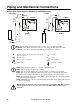
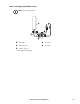
Piping and Mechanical Connections
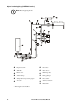
Refrigeration Piping Diagram (ACRD100 and ACRD500 series)
Note: Shutoff valves shown nearest to the condensers are not supplied by APC.
ACRD500 series: The shutoff valves nearest to the cooling unit are supplied by APC.
ACRD100 series: The shutoff valves are not supplied and must be ordered.
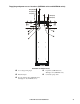
Note: Route piping through the top or bottom of the InRow RD.
Note: All lines are Type L ACR copper tubing.
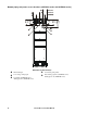
Note: Trap the vertical discharge line every 6 m (20 ft) to ensure proper oil return.
Note: Pipe size should change after the P-trap based on the recommended piping charts
provided with the installation manual. See the piping diagram created for your site.
Note: The maximum piping run is 61 m (200 ft) equivalent length. Size the piping pursuant
to accepted refrigeration practice.
Note: ACRD100 series only: any equivalent length greater than 46 m (150 ft) will result in a
5% decrease in capacity.
Warning: Do not install the air-cooled condenser below the InRow RD. The condenser
must be positioned above or at the same level as the InRow RD to ensure proper
function.
Pitch in direction of refrigerant flow; 4 mm per m
(1/2 in per 10 ft)
P-trap
Shutoff valves S-trap
Head pressure control valve Inverted P-trap
Check valve Pressure relief valve
na2543a
H
o
t
g
a
s
L
i
q
u
i
d
H
o
t
g
a
s
RD
RD
Receiver Receiver
Bottom piping
Top piping
Condenser Condenser
L
i
q
u
i
d