Installation Manual InfraStruXure® Central AP9465 AP9470 AP9475
This manual is available in English on the enclosed CD. Dieses Handbuch ist in Deutsch auf der beiliegenden CD-ROM verfügbar. Este manual está disponible en español en el CD-ROM adjunto. Ce manuel est disponible en français sur le CD-ROM ci-inclus. Questo manuale è disponibile in italiano nel CD-ROM allegato. 本マニュアルの日本語版は同梱の CD-ROM からご覧になれます。 O manual em Português está disponível no CD-ROM em anexo. Данное руководство на русском языке имеется на прилагаемом компакт-диске.
Contents Product Description........................................................ 1 Overview . . . . . . . . . . . . . . . . . . . . . . . . . . . . . . . . . . . . . . . . . . . . . . . . 1 Inventory . . . . . . . . . . . . . . . . . . . . . . . . . . . . . . . . . . . . . . . . . . . . . . . 1 Receiving inspection . . . . . . . . . . . . . . . . . . . . . . . . . . . . . . . . . . . . . 1 Please recycle . . . . . . . . . . . . . . . . . . . . . . . . . . . . . . . . . . . . . . . . . . . 1 Disclaimer .
Initial Configuration....................................................... 10 Configure the InfraStruXure Central Server. . . . . . . . . . . . . . . . . . . 10 System and Web browser prerequisites . . . . . . . . . . . . . . . . . . . . . 10 Configuring the InfraStruXure Central server from a remote computer 10 Enable Remote Monitoring . . . . . . . . . . . . . . . . . . . . . . . . . . . . . . . . 11 Product Information ......................................................
Product Description Overview Inventory • APC ® InfraStruXure™ Central server—A 1U or 2U management device. The InfraStruXure Central server works with your APC devices, NetBotz appliances, and other third-party SNMP devices to provide a comprehensive monitoring solution for your IT environment and equipment. The InfraStruXure Central appliance is available in Basic, Standard, or Enterprise models.
Safety Rack-mounting safety The InfraStruXure Central server is shipped with rack-mounting rails. Install the rails at the appropriate position in your rack, and mount the unit. If the unit is mounted in an enclosure instead of an open rack, the maximum ambient temperature in the enclosure should be no greater than 35°C (95°F). • When you install equipment in the rack, make sure it does not interfere with the air flow required for safe operation for the equipment.
Installation Installation Instructions This installation guide provides instructions for trained service technicians installing one or more systems in a rack. The provided RapidRails rack kit can be installed without tools in any enclosure that has square holes. One rack kit is required for each system installed in the rack. VersaRails™ rack kits, which are designed for use with enclosures that have round holes, are available for purchase separately.
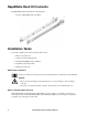
RapidRails Rack Kit Contents The RapidRails rack kit includes the following items: • One pair of RapidRails slide assemblies Installation Tasks To install a rack kit, perform the following tasks in order: 1. Remove the rack doors. 2. Select a location within the rack. 3. Install the RapidRails slide assemblies. 4. Install the system in the rack. 5. Replace the rack doors. Remove the rack doors See the procedures for removing doors in the documentation provided with your rack cabinet.
Install the RapidRails slide assemblies 1. At the front of the rack cabinet, position one of the RapidRails slide assemblies so that its mounting-bracket flange fits in one U-space in the rack. The top mounting hook on the slide assembly’s front mounting bracket flange should enter the top hole of the U-space. 2.
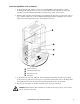
Install the system in the rack Caution: • If you are installing more than one system, install the first system in the lowest available position in the rack. • Never pull more than one component out of the rack at a time. • Because of the size and weight of the system, never attempt to install the system in the slide assemblies by yourself. 1. Pull the two slide assemblies out of the rack until they lock in the fully extended position.
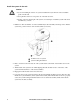
6. Press up on the slide release latch at the side of each slide to slide the system completely into the rack. 7. Push in and turn the captive thumbscrews on each side of the front chassis panel to secure the system to the rack. To remove the system from the slide assemblies, press down on the thumbpads of the system locking mechanism, and then pull the system forward. Replace the rack doors See the procedures for replacing doors in the documentation provided with your rack.
Route network cables to the InfraStruXure Central server and switch (or hub) Overhead routing. This section is for InfraStruXure system installations. 1. Ensure that the APC Shielding Partitions and Cable Ladders are installed on the NetShelter enclosures and the InfraStruXure PDUs. 2. Run the Cat-5 network cables (provided) from each APC device to the switch (or hub) a. Start with the device farthest from the switch (or hub) that uses the longest CAT-5 network cable. b.
Connect the InfraStruXure Central server to your Public LAN For InfraStruXure system installations, connect the InfraStruXure Central server’s Gb1 port (Standard version shown) to any network port on the user’s Public LAN, using a network jumper cable, or a standard network cable, if necessary. . Public LAN connection: Connect the InfraStruXure Central server to your Private LAN 1. Connect a port on your Private LAN to the InfraStruXure Central server’s Gb2 port (Standard version shown).
Initial Configuration Configure the InfraStruXure Central Server To configure the public LAN network settings on the InfraStruXure Central server for the first time, you must connect to the InfraStruXure Central server as follows: • Connect the private network port (Gb2) with a computer connected directly to the Gb2 port or connected to a switch (or hub) that is connected to the Gb2 port. .
Enable Remote Monitoring APC can remotely monitor your InfraStruXure Central server and the devices it manages, and notify you of events via e-mail, pager, or phone. If you decide to use APC’s Remote Monitoring Service (RMS), follow these steps:. Warning: Information that will be sent to the APC monitoring service must be entered in English. Any other language may prevent RMS from being able to properly notify of or describe any critical issues. 1.
Product Information InfraStruXure Central Front Panel Basic model (front) Item Function Diagnostic Indicators The four diagnostics indicators on the system front panel display error codes during system startup. Power-on Indicator, Power Button The power-on indicator lights when the system power is on. The power-on indicator blinks when the system is not turned on but power is available. The power button controls the power supply output to the system.
Standard model (front) Item Function DVD Drive Allows CD/DVD-based updates for software and firmware. (Not available on the Basic model) Diagnostic Indicators The four diagnostics indicators on the system front panel display error codes during system startup. Power-on Indicator, Power Button The power-on indicator lights when the system power is on. The power-on indicator blinks when the system is not turned on but power is available.
Enterprise model (front) Item Function Power-on Indicator, Power Button The power-on indicator lights when the system power is on. The power-on indicator blinks when the system is not turned on but power is available. The power button controls the power supply output to the system. NMI Button Used to troubleshoot software and device driver errors when using certain operating systems. This button can be pressed using the end of a paper clip.
InfraStruXure Central rear panel Basic model (rear) Item Function Power Socket Receptacle for power cord. Mouse PS/2 Mouse port Kbd PS/2 Keyboard port USB Ports (2) Used to connect USB 2.0-compliant devices to the system. Serial 9-pin Monitor External monitor port System Status LED and button The identification buttons on the front and back panels can be used to locate a particular system within a rack.
Standard Model (rear) Item 16 Function Power Socket Receptacle for power cord. Mouse PS/2 Mouse port Keyboard PS/2 Keyboard port USB Ports (2) Used to connect USB 2.0-compliant devices to the system. Serial Port 9-pin Monitor VGA monitor port System Status LED and button The identification buttons on the front and back panels can be used to locate a particular system within a rack.
Enterprise Model (rear) Item Function Serial Port 9-pin Monitor External monitor port USB Ports (2) Used to connect USB 2.0-compliant devices to the system. Gb1 Gigabit Ethernet port for connecting to the public LAN. Gb2 Gigabit Ethernet port for connecting to a private LAN. System Identification Button The identification buttons on the front and back panels can be used to locate a particular system within a rack.
Specifications InfraStruXure Central server Electrical Input 100–240 VAC; 50/60 Hz; 0.7 A to 0.5 A Physical Dimensions (H × W × D) Unit Shipping Basic: 4.5 × 48.3 × 54.6 cm (1.7 × 19 × 21.5 in) Standard: 4.5 × 48.3 × 54.6 cm (1.7 × 19 × 21.5 in) Enterprise: 7.6 × 48.3 × 68.6 cm (3 × 19 × 27 in) Basic: 30.5 × 63.5 × 88.9 cm (12 × 25 × 35 in) Standard: 30.5 × 63.5 × 88.9 cm (12 × 25 × 35 in) Enterprise: 38.1 × 63.5 × 91.4 cm (15 × 25 × 36 in) Weight Unit Shipping weight Basic: 11.
Appendix A: LED Error Codes Error Code Listing Overview The four diagnostics indicators on the system front panel display error codes during system startup. The following table lists the causes associated with these codes. Code Causes Possible processor failure. Memory failure. Possible expansion card failure. Possible video card failure. Hard drive failure. Possible USB failure. No memory modules detected. System board failure. Memory configuration error.
Possible expansion card failure. Other failure. The system is in a normal operating condition after POST.
Appendix B: Diagnostic Messages Message Listing Overview The system's control panel LCD provides status messages to signify when the system is operating correctly or when the system needs attention. The LCD lights blue to indicate a normal operating condition, and lights amber to indicate an error condition. The LCD scrolls a message that includes a status code followed by descriptive text..
E1618 PS # Predictive Power supply voltage is out of acceptable range; specified power supply is improperly installed or faulty. E161C PS # Input Lost Power source for specified power supply is unavailable, or out of acceptable range. E1620 PS # Input Range Power source for specified power supply is unavailable, or out of acceptable range. E1624 PS Redundancy The power supply subsystem is no longer redundant. If the last supply fails, the system will go down.
E2017 Timer Fail Timer refresh failure. E2018 Prog Timer Programmable interval timer error. E2019 Parity Error Parity error. E201A SIO Err SIO failure. E201B Kybd Controller Keyboard controller failure. E201C SMI Init System management interrupt (SMI) initialization failure. E201D Shutdown Test BIOS shutdown test failure. E201E POST Mem Test BIOS POST memory test failure. E201F DRAC Config Dell remote access controller (DRAC) configuration failure.
Warranties and Policies Two-Year Factory Warranty This warranty applies only to the products you purchase for your use in accordance with this manual. Terms of warranty APC warrants its products to be free from defects in materials and workmanship for a period of two years from the date of purchase. APC will repair or replace defective products covered by this warranty.
IN NO EVENT SHALL APC, ITS OFFICERS, DIRECTORS, AFFILIATES OR EMPLOYEES BE LIABLE FOR ANY FORM OF INDIRECT, SPECIAL, CONSEQUENTIAL OR PUNITIVE DAMAGES, ARISING OUT OF THE USE, SERVICE OR INSTALLATION, OF THE PRODUCTS, WHETHER SUCH DAMAGES ARISE IN CONTRACT OR TORT, IRRESPECTIVE OF FAULT, NEGLIGENCE OR STRICT LIABILITY OR WHETHER APC HAS BEEN ADVISED IN ADVANCE OF THE POSSIBILITY OF SUCH DAMAGES.
Hospital-grade wiring devices and leakage current protection may be ordered as options on many APC UPS systems. APC does not claim that units with these modifications are certified or listed as hospitalgrade by APC or any other organization. Therefore these units do not meet the requirements for use in direct patient care.
APC Worldwide Customer Support Customer support for this or any other APC product is available at no charge in any of the following ways: • Visit the APC Web site to access documents in the APC Knowledge Base and to submit customer support requests. – www.apc.com (Corporate Headquarters) Connect to localized APC Web sites for specific countries, each of which provides customer support information. – www.apc.com/support/ Global support searching APC Knowledge Base and using e-support.