InRoom™ Precision Air Conditioner Technical Data ACPDX21-86, ACPCW40-150
American Power Conversion Legal Disclaimer The information presented in this manual is not warranted by the American Power Conversion Corporation to be authoritative, error free, or complete. This publication is not meant to be a substitute for a detailed operational and site specific development plan.
Contents Overview ..................................................................................................... 1 General . . . . . . . . . . . . . . . . . . . . . . . . . . . . . . . . . . . . . . . . . . . . . . . . . . . . . . .1 Scalable Solution for Critical Environments . . . . . . . . . . . . . . . . . . . . . . . . .2 Standard Features . . . . . . . . . . . . . . . . . . . . . . . . . . . . . . . . . . . . . . . . . . . . . .3 Optional Features. . . . . . . . . . . . . . . . . . . . . . . .
InRoom Nomenclature Product Range Cooling System Model Size Number of Refrigeration Circuits Airflow Pattern D - Downflow, U - Upflow 0, 1, 2 DX: 21, 31, 45, 61, 86 CW: 40, 66, 90, 110, 150 P = Perimeter unit A: Air-cooled G: Glycol-cooled ACW: Air-cooled with MultiCool GCW: Glycol-cooled with MultiCool GE: Glycol-cooled with Economizer CW: Chilled Water Voltage Phase/Hertz Reheat Humidification Mains Input Selection X - None, E - Immersed Electrode X - None, E - Electric A: 3/60 B: 3/50 B: 208-230V G:
Overview General The InRoom product family is an assemble to order (ATO) line of perimeter air conditioning systems that provide precision cooling for data centers and server rooms. Precision environmental close control requirements now reach far beyond the confines of the traditional data center or computer room to encompass a larger suite of applications, referred to as technology rooms.
Scalable Solution for Critical Environments Temperature and Humidity Design Conditions Maintenance of temperature and humidity design conditions is critical to the smooth operation of a technology room. Based on ASHRAE TC9.9, the recommended design conditions for class one and class two environments should be 20–25°C (68–77°F) and 40–55% relative humidity (R.H.). Precision air conditioning is designed to maintain temperature at ±2°F and humidity at ±3–5% R.H. 24 hours a day, 365 days a year.
Standard Features Insulated Panels The frame is constructed of 16 gauge steel sheet metal for maximum strength. All exterior panels and corner posts on the frame are powder coated for durability and an attractive finish. The side panels are double wall construction (inner and outer panels) with insulation between. The insulation is 12 mm (1/2 in) thick fiberglass. The walls isolate the insulation from the air stream and further reduce sound levels. Panels are hinged and removable for easy access.
Optional Features Humidifier Hot Gas Bypass Valve Plenums The humidifier utilizes a pure steam generator specifically designed for precision environmental close control. The pure steam eliminates contaminating mineral deposits, potentially harmful bacteria, white dust, and excessive humidity. The humidifier requires little scheduled maintenance. The humidifier is proportionally controlled to meet the humidification demands of the conditioned space. Humidifier canisters are replaceable.
na2857a na2867a Condensate Pump 50 Hz 60 Hz Model # ACAC75107 ACAC75107 ACAC76106 Hz 60 60 50 Height mm (in) 259 (10 1/8) 259 (10 1/8) 210 (8 1/4) Width mm (in) 152 (6) 152 (6) 132 (5 1/4) Length 304 (12) 304 (12) 295 (11 1/2) Outlet mm (in) 13 (1/2) 13 (1/2) 6 (1/4) Volts 230 460 400 Amps 1.9 0.8 0.125 Watts 360 360 30 Weight Kg (Lb) Ea 5.8 (13) 5.8 (13) 3 (6.6) HP (motor only) 1/5 1/5 1/20 Tank Capacity Ltr (Gal) 3.785 (1) 3.785 (1) 1.
na2874a Upflow Discharge Plenums for 50 Hz and 60 Hz InRoom Cooling Units Upflow discharge plenums Cabinet size 1 2 3 4 5 SKU ACPL75100 ACPL75101 ACPL75102 ACPL75103 ACPL75104 Width mm (in) Depth mm (in) Height mm (in) 1000 (39.37) 1400 (55.11) 1750 (68.90) 2150 (84.65) 2550 (100.39) 900 (35) 500 (19.7) Note: Plenums are delivered completely assembled.
na3026a Downflow Discharge Plenums for 50 Hz InRoom Cooling Units Width Depth Cabinet size SKU mm (in) mm (in) Unit Sub Base Plenum with no Grills 1 ACSB76100 960 (37.8) 2 ACSB76101 1360 (53.5) 3 ACSB76102 1710 (67.3) 865 (34) 4 ACSB76103 2110 (83.1) 5 ACSB76104 2510 (98.8) Unit Sub Base Plenum with Grills 1 ACSB76110 960 (37.8) 2 ACSB76111 1360 (53.5) 3 ACSB76112 1710 (67.3) 865 (34) 4 ACSB76113 2110 (83.1) 5 ACSB76114 2510 (98.8) Unit Sub Base Plenum with Damper (50Hz only) 1 ACSB76120 960 (37.
na2834a Standard Floorstands for InRoom 60Hz Cooling Units Cabinet size 1 2 3 4 5 8 Model Height mm (in) Width mm (in) ACFS76000 ACFS76001 ACFS76002 ACFS76003 ACFS76004 ACFS76005 ACFS76006 ACFS76007 ACFS76008 ACFS76009 ACFS76010 ACFS76011 ACFS76012 ACFS76013 ACFS76014 ACFS76015 ACFS76016 ACFS76017 ACFS76018 ACFS76019 ACFS76020 ACFS76021 ACFS76022 ACFS76023 ACFS76024 254 (10) 305 (12) 381 (15) 457 (18) 609 (24) 254 (10) 305 (12) 381 (15) 457 (18) 609 (24) 254 (10) 305 (12) 381 (15) 457 (18) 609
na3053a Bowling Alley Floorstands for InRoom 60Hz Cooling Units Cabinet size 1 2 3 4 5 Model Height mm (in) ACFS76033 ACFS76032 ACFS76031 ACFS76030 ACFS76037 ACFS76036 ACFS76035 ACFS76034 ACFS76041 ACFS76040 ACFS76039 ACFS76038 ACFS76045 ACFS76044 ACFS76043 ACFS76042 ACFS76049 ACFS76048 ACFS76047 ACFS76046 305 (12) 381 (15) 457 (18) 609 (24) 305 (12) 381 (15) 457 (18) 609 (24) 305 (12) 381 (15) 457 (18) 609 (24) 305 (12) 381 (15) 457 (18) 609 (24) 305 (12) 381 (15) 457 (18) 609 (24) Width mm (in)
na3087a Floorstands for InRoom 50 HzCooling Units 10 Cabinet size Model Height mm (in) Width mm (in) Depth mm (in) 1 2 3 4 5 ACFS76025 ACFS76026 ACFS76027 ACFS76028 ACFS76029 250-500 (10-20) 250-500 (10-20) 250-500 (10-20) 250-500 (10-20) 250-500 (10-20) 960 (37.8) 1359 (53.5) 1712 (67.4) 2108 (83.0) 2512 (98.
Condensers Air cooled condensers are designed to reject heat from refrigerant based cooling equipment and are designed to be installed outdoors. The condensers are self-contained in a lighweight aluminum cabinet designed for mounting to a horizontal surface. The cabinet houses condenser coils and fan assemblies. Each condenser coil is a copper turb, aluminum finned coil. The capacity of the condenser is based on the rated capacity of the coil.
InRoom Standard Condensers - 60 Hz InRoom Remote Outdoor Condenser Data, 95°F ambient, 120°F condensation - R407C InRoom Cabinet Size 1 2 3 4 Total Heat Rejection 96.219 165.496 225.435 279.262 (THR) BTU/h CFM 8,394 19,325 18,609 17,604 Fan Diameter - in 19.69 24.80 24.80 24.80 Voltage Options 208-230/3/60 ACCD76000 ACCD76004 ACCD76008 ACCD76012 Number of Fans 2 2 2 2 Fan RPM (Qty) 1490 1585(1), 1500(1) 1585(1), 1500(1) 1585(1), 1500(1) Motor HP (Qty) 1.23 Hp(2) 3.58(1), 3.85(1) 3.58(1), 3.85(1) 3.58(1), 3.
InRoom Low Temperature (-30ºF) Condensers - 60 Hz InRoom Remote Outdoor Condenser Data, 95°F ambient, 120°F condensation - R407C InRoom Cabinet Size 1 2 3 4 Total Heat Rejection 96.219 165.496 225.435 279.262 (THR) BTU/h CFM 8,394 19,325 18,609 17,604 Fan Diameter - in 19.69 24.80 24.80 24.80 Voltage Options 208-230/3/60 ACCD76032 ACCD76033 ACCD76034 ACCD76035 Number of Fans 2 2 2 2 Fan RPM (Qty) 1490 1585(1), 1500(1) 1585(1), 1500(1) 1585(1), 1500(1) Motor HP (Qty) 1.23(2) 3.58(1), 3.85(1) 3.58(1), 3.
InRoom High Temperature Condensers - 60 Hz InRoom Remote Outdoor Condenser Data, 105°F ambient, 125°F condensation - R407C InRoom Cabinet Size 1 2 3 4 Total Heat Rejection 154,105 247,501 331,845 448,600 (THR) BTU/h CFM 19,325 17,604 27,791 25,227 Fan Diameter - in 25.60 25.60 25.60 25.60 Voltage Options 208-230/3/60 ACCD76004 ACCD76006 ACCD76016 ACCD76014 Number of Fans 2 2 3 3 Fan RPM (Qty) 1585(1), 1500(1) 1585(1), 1500(1) 1585(2), 1500(1) 1585(1), 1350(1) Motor HP (Qty) 3.58(1), 3.85(1) 3.58(1), 3.
InRoom Condensers - 50 Hz na2856a 50 Hz InRoom Remote Outdoor Condenser Data, 97°F ambient, 120°F condensation - R407C InRoom Cabinet Size 1 2 3 4 Condenser Model (Qty) ACCD76002 ACCD76003 ACCD76002 (2) ACCD76003 (2) Voltage 230/1/50 230/1/50 230/1/50 230/1/50 Number of Fans 2 2 3 3 3 Airflow m /h (cfm) 13600 (8024) 13000 (7670) 13600 (8024) each 13000 (7670) each 2 x 0.69 2 x 0.69 2 x 0.69 2 x 0.69 Motor kW (HP) (2 x 0.92) (2 x 0.92) (2 x 0.92) (2 x 0.
Receivers Conformance. Each receiver conforms to UL, CSA or ASME requirements for 450 psi maximum working pressure. Models with an internal diameter under six inches are UL listed. All larger models are made according to ASME code and labeled appropriately. Pumpdown and refrigerant charge. All pumpdowns are calculated at 80% capacity of liquid. Approximately 10% of pumpdown capacity is required to operate the receiver properly.
InRoom Receivers - 50 Hz 50 Hz InRoom Cabinet Size 50 Hz Air-Cooled Condenser Model 50 Hz Receiver Model (Qty) Max Refrigerant Charge 90% at 20°C (68°F) R-407C kg (lb) * Connection inlet - mm (in) Connection thread/flange Connection outlet - mm (in) Gauge Pressure relief valve connection Height - mm (in) Depth - mm (in) Width - mm (in) Weight - kg (lb) 1 2 ACCD76002 ACCD76003 ACCD76002 (2) ACCD76003 (2) ACCD76011 (2) ACAC76101 ACAC76102 ACAC76103 (2) ACAC76104 (2) 24.0 (53) 24.
Display Interface The display interface is standard on each system. The display interface provides precision control for the demanding requirements of these environments: Data centers Control rooms Clean rooms Switch rooms UPS rooms na2773a • • • • • The easy-to-use display allows the operator to select options from the display interface to control and monitor the InRoom precision air conditioning system. Logging The display interface displays the most recent alarms.
InRoom Model Sizes Different variations of the InRoom product range are defined by the airflow direction, the number of refrigerant circuits, and the type of cooling system. There are five cabinet sizes. The front service access for all cabinet sizes of the InRoom Precision Air Conditioner is 1 m (39 in). The InRoom Fluid Cooled (Glycol) system with Economizer Coil differs from the other versions by having a larger cabinet size, not a larger capacity.
InRoom Cooling Unit Configurations Fluid Cooled (Glycol) • System is used with a fluid cooler. • Factory-tested as a sealed system. • Eliminates the need for field refrigerant piping. • No requirement for water treatment. • Economizer option provides high efficiency. • Low maintenance. na2837a InRoom Fluid Cooled (Glycol) systems are completely charged and factory tested in a sealed system for reliability.
na2843a The InRoom Fluid Cooled (Glycol) System with Chilled Water System is a combination of a factory sealed glycol system and a chilled water system and contains two separate cooling coils. The controller microprocessor manages the systems to allow the glycol system to operate as standby to the chilled water system or vice versa, giving the added security of back-up cooling to the computer room.
Air cooled systems are not pre-charged from the factory and require field refrigerant piping. Each installation requires an engineered piping solution. APC strongly recommends installation by a highly qualified refrigeration contractor to avoid improper elevation and long piping runs. The Air Cooled system uses refrigerant as the heat transfer medium. Room air recirculates through the InRoom unit which houses the evaporator coil, scroll compressor, and refrigeration system.
60Hz Performance Specifications Chilled Water (CW) – 60Hz Chilled Water PCW400 Cabinet Size 1 26.7°C DB, 19.4°C WB (80°F DB, 67°F WB) 50% RH Total - kW (BTU/hr) 53.6 (182,800) Sensible - kW (BTU/hr) 35.8 (128,999) Flow Rate - L/m (GPM) 139.3 (36.8) Total Pressure Drop Water Side - Kpa (ft) 91.8 (30.7) 23.9°C DB, 16.9°C WB (75°F DB, 62.5°F WB) 50% RH Total - kW (BTU/hr) 29.4 (100,300) Sensible - kW (BTU/hr) * 25.5 (93,799) Flow Rate - L/m (GPM) 80.3 (21.2) Total Pressure Drop Water Side - Kpa (ft) 29.6 (9.
Chilled Water Continued PCW400 PCW660 PCW900 PCW1100 PCW1500 Cabinet Size 1 Cabinet Size 2 Cabinet Size 3 Cabinet Size 4 Cabinet Size 5 Fan Information Number of Fans 1 Air Flow - M³/hr (CFM) 8495 (5,000) External Static Pressure - Pa (in WC) 50 (0.2) Sound Power Level - dBA 72.1 Total Fan Power Consumption - kW (hp) 1.7 (2.
Air Cooled (DX) System – 60Hz Air Cooled PA211 PA311 PA452 PA612 Cabinet Size 1 Cabinet Size 2 Cabinet Size 3 Cabinet Size 4 26.7°C DB, 19.4°C WB (80°F DB, 67°F WB) 50% RH Total - kW (BTU/hr) 19.8 (67,450) 29.9 (102,000) 44.2 (151,000) 55.2 (188,290) Sensible - kW (BTU/hr) 19.8 (67,450) 29.9 (102,000) 41.3 (141,000) 55.2 (188,290) 23.9°C DB, 16.9°C WB (75°F DB, 62.5°F WB) 50% RH Total - kW (BTU/hr) 18.1 (61,940) 27.6 (94,000) 40.5 (138,000) 50.8 (173,470) Sensible - kW (BTU/hr) * 18.1 (61,940) 27.
Air Cooled (DX) Continued PA211 PA311 PA452 PA612 PA862 Cabinet Size 1 Cabinet Size 2 Cabinet Size 3 Cabinet Size 4 Cabinet Size 5 Fan Information Number of Fans 1 Air Flow - M³/hr (CFM) 7493 (4,410) External Static Pressure - Pa (in WC) 50 (0.2) Sound Power Level - dBA 75.40 Total Fan Power Consumption - kW (hp) 1.7 (2.3) Connection Sizes Number of DX Circuits 1 Liquid Line O.D. - mm (in) 12 (1/2) Discharge Line O.D.
MultiCool – Air Cooled (DX) with CW – 60Hz Operational Mode: Air Cooled (DX) Net Cooling Capacity PACW211 PACW311 PACW452 PACW612 Cabinet Size 1 Cabinet Size 2 Cabinet Size 3 Cabinet Size 4 26.7°C DB, 19.4°C WB (80°F DB, 67°F WB) 50% RH Total - kW (BTU/hr) 19.2 (65,455) 29.7 (101,460) 43.7 (149,150) 54.5 (186,105) Sensible - kW (BTU/hr) 19.2 (65,455) 29.7 (101,460) 40.8 (139,365) 54.5 (186,105) 23.9°C DB, 16.9°C WB (75°F DB, 62.5°F WB) 50% RH Total - kW (BTU/hr) 17.8 (60,895) 27.6 (94,050) 40.
Operational Mode: Chilled Water (CW) Net Cooling Capacity - 7.2°C (45°F) EWT PACW211 Cabinet Size 1 26.7°C DB, 19.4°C WB (80°F DB, 67°F WB) 50% RH Total - kW (BTU/hr) 34.3 (117,040) Sensible - kW (BTU/hr) 25.9 (88,540) Flow Rate - L/m (GPM) 98.4 (26.0) Total Pressure Drop Water Side - Kpa (ft) 88.8 (29.7) 23.9°C DB, 16.9°C WB (75°F DB, 62.5°F WB) 50% RH Total - kW (BTU/hr) 20.0 (68,115) Sensible - kW (BTU/hr) * 20.0 (68,115) Flow Rate - L/m (GPM) 59.4 (15.7) Total Pressure Drop Water Side Kpa (ft) 32.
Information common to both modes PACW211 PACW311 PACW452 PACW612 PACW862 Cabinet Size 1 Cabinet Size 2 Cabinet Size 3 Cabinet Size 4 Cabinet Size 5 Connection Sizes Humidifier Supply Line - mm (in) 6 (1/4) Condensate Drain Line - mm OD (in ID) 21 (3/4) Fan Information Number of Fans 1 Air Flow M³/hr (CFM) 7034 (4,140) External Static Pressure - Pa (in WC) 50 (0.2) Sound Power Level - dBA 76.6 Total Fan Power Consumption - kW (hp) 2.0 (2.
Fluid Cooled (Glycol 40%) – 60Hz Net Cooling Capacity PG211 PG311 PG452 PG612 Cabinet Size 1 Cabinet Size 2 Cabinet Size 3 Cabinet Size 4 26.7°C DB, 19.4°C WB (80°F DB, 67°F WB) 50% RH Total - kW (BTU/hr) 19.8 (67,450) 30.0 (102,410) 44.2 (150,785) 55.2 (188,290) Sensible - kW (BTU/hr) 19.8 (67,450) 30.0 (102,410) 41.3 (140,980) 55.2 (188,290) 23.9°C DB, 16.9°C WB (75°F DB, 62.5°F WB) 50% RH Total - kW (BTU/hr) 18.1 (61,940) 27.8 (95,000) 40.5 (138,130) 50.8 (173,470) Sensible - kW (BTU/hr) * 18.
Fluid Cooled (Glycol 40%) Continued PG211 PG311 PG452 PG612 Cabinet Size 1 Cabinet Size 2 Cabinet Size 3 Cabinet Size 4 Fan Information Number of Fans 1 Air Flow - M³/hr (CFM) 7493 (4,410) External Static Pressure - Pa (in WC) 50 (0.2) Sound Power Level - dBA 75.4 Total Fan Power Consumption - kW (hp) 1.7 (2.3) Condenser Data Total Heat Rejection (THR) - kW (BTU/hr) 27.4 (93,400) Flow rate - L/m (GPM) 61.7 (16.3) Total pressure drop water side - kPa (ft) 87.3 (29.2) Valve size - mm (in) 20 (0.
Fluid Cooled (Glycol 0%) – 60Hz Net Cooling Capacity PG211 PG311 PG452 PG612 Cabinet Size 1 Cabinet Size 2 Cabinet Size 3 Cabinet Size 4 26.7°C DB, 19.4°C WB (80°F DB, 67°F WB) 50% RH Total - kW (BTU/hr) 19.8 (67,450) 30.0 (102,410) 44.2 (151,765) 55.2 (188,290) Sensible - kW (BTU/hr) 19.8 (67,450) 30.0 (102,410) 41.3 (140,098) 55.2 (188,290) 23.9°C DB, 16.9°C WB (75°F DB, 62.5°F WB) 50% RH Total - kW (BTU/hr) 18.1 (61,940) 27.8 (95,000) 40.5 (138,130) 50.8 (173,470) Sensible - kW (BTU/hr) * 18.
Fluid Cooled (Glycol 0%) Continued PG211 PG311 PG452 PG612 PG862 Cabinet Size 1 Cabinet Size 2 Cabinet Size 3 Cabinet Size 4 Cabinet Size 5 Fan Information Number of Fans Air Flow - M³/hr (CFM) External Static Pressure - Pa (in WC) Sound Power Level - dBA Total Fan Power Consumption - kW (hp) Condenser Data Total Heat Rejection (THR) - kW (BTU/hr) Flow rate - L/m (GPM) Total pressure drop water side - kPa (ft) Valve size - mm (in) Connection Sizes Condenser In/Out - mm (in) Humidifier Supply Line - mm (in
Fluid Cooled (Glycol 0%) with CW – 60Hz Operational Mode: Fluid Cooled (Glycol 0%) Net Cooling Capacity PGCW211 PGCW311 PGCW452 PGCW612 Cabinet Size 1 Cabinet Size 2 Cabinet Size 3 Cabinet Size 4 26.7°C DB, 19.4°C WB (80°F DB, 67°F WB) 50% RH Total - kW (BTU/hr) 19.5 (66,405) 29.7 (101,460) 43.7 (149,150) 54.3 (185,440) Sensible - kW (BTU/hr) 19.5 (66,405) 29.7 (101,460) 40.8 (139,365) 54.3 (185,440) 23.9°C DB, 16.9°C WB (75°F DB, 62.5°F WB) 50% RH Total - kW (BTU/hr) 17.8 (60,895) 27.6 (94,050) 40.
Operational Mode: Chilled Water (CW) Net Cooling Capacity -7.2°C (45°F) EWT PGCW211 Cabinet Size 1 26.7°C DB, 19.4°C WB (80°F DB, 67°F WB) 50% RH Total - kW (BTU/hr) 34.3 (117,040) Sensible - kW (BTU/hr) 25.9 (88,540) Flow Rate - L/m (GPM) 98.4 (26.0) Total pressure drop water side - kPa (ft) 88.8 (29.7) 23.9°C DB, 16.9°C WB (75°F DB, 62.5°F WB) 50% RH Total - kW (BTU/hr) 20.0 (68,115) Sensible - kW (BTU/hr) * 20.0 (68,115) Flow Rate - L/m (GPM) 59.4 (15.7) Total pressure drop water side - kPa (ft) 32.
Information common to both modes PGCW211 PGCW311 PGCW452 PGCW612 PGCW862 Cabinet Size 1 Cabinet Size 2 Cabinet Size 3 Cabinet Size 4 Cabinet Size 5 Connection Sizes Condenser In/Out - mm (in) 28 (1 1/8) Humidifier Supply Line - mm (in) 6 (1/4) Condensate Drain Line - mm OD (in ID) 21 (3/4) Fan Information Number of Fans 1 Air Flow - M³/hr (CFM) 125 (4,410) External Static Pressure - Pa (in WC) 50 (0.2) Sound Power Level - dBA 72.5 Total Fan Power Consumption - kW (hp) 2.0 (2.
Fluid Cooled (Glycol 40%) with CW – 60Hz Operational Mode: Fluid Cooled (Glycol 40%) Net Cooling Capacity PGCW211 PGCW311 PGCW452 PGCW612 Cabinet Size 1 Cabinet Size 2 Cabinet Size 3 Cabinet Size 4 26.7°C DB, 19.4°C WB (80°F DB, 67°F WB) 50% RH Total - kW (BTU/hr) 19.4 (66,120) 29.7 (101,460) 43.7 (149,150) 54.3 (185,440) Sensible - kW (BTU/hr) 19.4 (66,120) 29.7 (101,460) 40.8 (139,365) 54.3 (185,440) 23.9°C DB, 16.9°C WB (75°F DB, 62.5°F WB) 50% RH Total - kW (BTU/hr) 17.8 (60,895) 27.6 (94,050) 40.
Operational Mode: Chilled Water (CW) Net Cooling Capacity -7.2°C (45°F) EWT PGCW211 Cabinet Size 1 26.7°C DB, 19.4°C WB (80°F DB, 67°F WB) 50% RH Total - kW (BTU/hr) 34.3 (117,040) Sensible - kW (BTU/hr) 25.9 (88,540) Flow Rate - L/m (GPM) 98.4 (26.0) Total pressure drop water side - kPa (ft) 88.8 (29.7) 23.9°C DB, 16.9°C WB (75°F DB, 62.5°F WB) 50% RH Total - kW (BTU/hr) 20.0 (68,115) Sensible - kW (BTU/hr) * 20.0 (68,115) Flow Rate - L/m (GPM) 59.4 (15.7) Total pressure drop water side - kPa (ft) 32.
Information common to both modes PGCW211 PGCW311 PGCW452 PGCW612 PGCW862 Cabinet Size 1 Cabinet Size 2 Cabinet Size 3 Cabinet Size 4 Cabinet Size 5 Connection Sizes Condenser In/Out - mm (in) 28 (1 1/8) Humidifier Supply Line - mm (in) 6 (1/4) Condensate Drain Line - mm OD (in ID) 21 (3/4) Fan Information Number of Fans 1 Air Flow - M³/hr (CFM) 125 (4,410) External Static Pressure - Pa (in WC) 50 (0.2) Sound Power Level - dBA 72.5 Total Fan Power Consumption - kW (hp) 2.0 (2.
Fluid Cooled (Glycol 40%) with Economizer - 60Hz Operational Mode: Fluid Cooled (Glycol 40%) - Summer Net Cooling Capacity PGE211 Cabinet Size 2 PGE311 Cabinet Size 3 PGE452 Cabinet Size 4 PGE612 Cabinet Size 5 26.7°C DB, 19.4°C WB (80°F DB, 67°F WB) 50% RH Total - kW (BTU/hr) 20.0 (68,115 31.1 (106,305) 45.6 (155,610) 58.6 (196,745) Sensible - kW (BTU/hr) 20.0 (68,115) 31.1 (106,305) 43.1 (147,000) 58.6 (196,745) 23.9°C DB, 16.9°C WB (75°F DB, 62.5°F WB) 50% RH Total - kW (BTU/hr) 19.2 (65,455) 28.
Operational Mode: Fluid Cooled (Glycol 40%) - Winter Net Cooling Capacity PGE211 Cabinet Size 2 26.7°C DB, 19.4°C WB (80°F DB, 67°F WB) 50% RH Total - kW (BTU/hr) 20.0 (68,115) Sensible - kW (BTU/hr) 20.0 (68,115) Flow rate - L/m (GPM) 60.2 (22.9) Total pressure drop water side - kPa (ft) 31.1 (10.4) 23.9°C DB, 16.9°C WB (75°F DB, 62.5°F WB) 50% RH Total - kW (BTU/hr) 17.6 (59,945) Sensible - kW (BTU/hr) * 17.6 (59,945) Flow rate - L/m (GPM) 60.2 (22.9) Total pressure drop water side - kPa (ft) 31.1 (10.
Information common to both modes Connection Sizes Humidifier Supply Line - mm (in) Condensate Drain Line - mm OD (in ID) Fan Information Number of Fans Air Flow - M³/hr (CFM) External Static Pressure - Pa (in WC) Sound Power Level - dBA Total Fan Power Consumption - kW (hp) Humidification – Solid State Electrode, Canister Flush Cycle kg/hr (lb/hr) Electric Reheat – Equally Loaded Three (3) phase Capacity - kW (BTU/hr) - Includes Motor Heat 460 V 230 V Number of Stages Downflow Filters - mm 1050 x 453 x 47 G
60Hz InRoom Electrical Specifications Air Cooled (DX) and Fluid Cooled (Glycol) Electrical Data With Reheat and Humidification Model Size 211 Airflow Pattern Up/ Down Cooling System PAXXX PGXXX PACWXXX PGCWXXX PGEXXX 311 Up/ Down PAXXX PGXXX PACWXXX PGCWXXX PGEXXX 452 Up/ Down PAXXX PGXXX PACWXXX PGCWXXX PGEXXX 612 Up/ Down PAXXX PGXXX PACWXXX PGCWXXX PGEXXX 862 Up/ Down PAXXX PGXXX PACWXXX PGCWXXX Without Reheat and Humidification Compressor Data Voltage (3ph/60Hz) MCA MOP Power (kW)
Chilled Water (CW) Electrical Data With Reheat and Humidification Model Size 400 400 660 900 1100 1500 Airflow Pattern Down Up Up/Down Up/Down Up/Down Up/Down Cooling System PCWXXX PCWXXX PCWXXX PCWXXX PCWXXX PCWXXX Without Reheat and Humidification Voltage (3ph/60Hz) MCA MOP Power (kW) MCA MOP Power (kW) 208-230 59.0 60 18.8 9.9 15 3.1 460-480 32.7 35 20.8 4.4 15 2.8 575-600 28.7 30 22.9 6.2 15 4.9 208-230 60.6 70 19.3 11.5 20 3.7 460-480 33.
50Hz Performance Specifications Chilled Water (CW) - 50Hz Net Cooling Capacity PCW400 Cabinet Size 1 26.7°C DB, 19.4°C WB (80°F DB, 67°F WB) 50% RH Total - kW (BTU/hr) 53.6(182,800) Sensible - kW (BTU/hr) 35.8 (128,999) Flow Rate - L/m (GPM) 139.3 (36.8) Total Pressure Drop Water Side - Kpa (ft) 91.8 (30.7) 23.9°C DB, 16.9°C WB (75°F DB, 62.5°F WB) 50% RH Total - kW (BTU/hr) 27.4 (100,300) Sensible - kW (BTU/hr) * 25.5 (93,799) Flow Rate - L/sm(GPM) 80.0 (21.2) Total Pressure Drop Water Side - Kpa (ft) 29.
Chilled Water Continued PCW400 Cabinet Size 1 Fan Information Number of Fans 1 Air Flow - M³/hr (CFM) 8495 (5,000) External Static Pressure - Pa (in WC) 50 (0.2) Sound Power Level - dBA 72.1 Total Fan Power Consumption - kW (hp) 1.7 (2.
Air Cooled (DX) System - 50Hz Net Cooling Capacity PA211 PA311 PA452 PA612 Cabinet Size 1 Cabinet Size 2 Cabinet Size 3 Cabinet Size 4 26.7°C DB, 19.4°C WB (80°F DB, 67°F WB) 50% RH Total - kW (BTU/hr) 18.9 (64,505) 28.4 (96,900) 41.8 (142,595) 53.9 (184,110) Sensible - kW (BTU/hr) 18.9 (64,505) 28.4 (96,900) 41.8 (142,595) 53.9 (184,110) 23.9°C DB, 16.9°C WB (75°F DB, 62.5°F WB) 50% RH Total - kW (BTU/hr) 17.7 (60,325) 26.1 (89,110) 38.7 (132,240) 49.7 (169,575) Sensible - kW (BTU/hr) * 17.7 (60,325) 26.
Air Cooled Continued PA211 PA311 PA452 PA612 PA862 Cabinet Size 1 Cabinet Size 2 Cabinet Size 3 Cabinet Size 4 Cabinet Size 5 Fan Information Number of Fans 1 Air Flow - M³/hr (CFM) 7493 (4,410) External Static Pressure - Pa (in WC) 50 (0.2) Sound Power Level - dBA 75.40 Total Fan Power Consumption - kW (hp) 1.7 (2.3) Connection Sizes Number of DX Circuits 1 Air Liquid Line O.D. - mm (in) 12 (1/2) Air Discharge Line O.D.
MultiCool - Air Cooled (DX) with CW - 50Hz Operational Mode: Air (DX) Net Cooling Capacity PACW211 PACW311 PACW452 PACW612 Cabinet Size 1 Cabinet Size 2 Cabinet Size 3 Cabinet Size 4 26.7°C DB, 19.4°C WB (80°F DB, 67°F WB) 50% RH Total - kW (BTU/hr) 19.5 (66,405) 28.2 (95,235) 41.3 (140,980) 53.3 (181,830) Sensible - kW (BTU/hr) 19.5 (66,405) 28.2 (95,235) 41.3 (140,980) 53.3 (181,830) 23.9°C DB, 16.9°C WB (75°F DB, 62.5°F WB) 50% RH Total - kW (BTU/hr) 17.4 (59,280) 25.9 (88,540) 38.3 (130,625) 49.
Operational Mode: Chilled Water Net Cooling Capacity - 7.2°C (45°F) EWT PACW211 Cabinet Size 1 26.7°C DB, 19.4°C WB (80°F DB, 67°F WB) 50% RH Total - kW (BTU/hr) 34.3 (117,040) Sensible - kW (BTU/hr) 25.9 (88,540) Flow Rate - L/m (GPM) 98.4 (26.0) Total Pressure Drop Water Side - Kpa (ft) 88.8 (29.7) 23.9°C DB, 16.9°C WB (75°F DB, 62.5°F WB) 50% RH Total - kW (BTU/hr) 20.0 (68,115) Sensible - kW (BTU/hr) * 20.0 (68,115) Flow Rate - L/m (GPM) 59.4 (15.7) Total Pressure Drop Water Side - Kpa (ft) 32.0 (10.
Information common to both modes PACW211 PACW311 PACW452 PACW612 PACW862 Cabinet Size 1 Cabinet Size 2 Cabinet Size 3 Cabinet Size 4 Cabinet Size 5 Connection Sizes Humidifier Supply Line - mm (in) 6 (1/4) Condensate Drain Line - mm OD (in ID) 21 (3/4) Fan Information Number of Fans 1 Air Flow - M³/hr (CFM) 7034 (4,140) External Static Pressure - Pa (in WC) 50 (0.2) Sound Power Level - dBA 76.6 Total Fan Power Consumption - kW (hp) 2.0 (2.
Fluid Cooling (Glycol 40%) – 50Hz Net Cooling Capacity - 40.5°C (105°F) EWT PG211 PG311 PG452 PG612 Cabinet Size 1 Cabinet Size 2 Cabinet Size 3 Cabinet Size 4 26.7°C DB, 19.4°C WB (80°F DB, 67°F WB) 50% RH Total - kW (BTU/hr) 18.9 (64,505) 28.5 (97,280) 41.8 (142,595) 53.9 (184,110) Sensible - kW (BTU/hr) 18.9 (64,505) 28.5 (97,280) 41.8 (142,595) 53.9 (184,110) 23.9°C DB, 16.9°C WB (75°F DB, 62.5°F WB) 50% RH Total - kW (BTU/hr) 17.7 (60,325) 26.2 (89,490) 38.7 (132,240) 49.
Fluid Cooled (Glycol 40%) Continued PG211 PG311 PG452 PG612 PG862 Cabinet Size 1 Cabinet Size 2 Cabinet Size 3 Cabinet Size 4 Cabinet Size 5 Fan Information Number of Fans 1 1 2 Air Flow - M³/hr (CFM) 7493 (4,410) 10007 (5,890) 14000 (8,240) External Static Pressure - Pa (in WC) 50 (0.2) 50 (0.2) 50 (0.2) Sound Power Level - dBA 75.4 79.2 77.4 Total Fan Power Consumption - kW (hp) 1.7 (2.3) 2.0 (2.7) 3.1 (4.2) Condenser Data (40% Glycol inlet temperature 40.5°C (105°F), outlet temperature 46.
Fluid Cooled (Glycol 0%) – 50Hz Net Cooling Capacity PG211 PG311 PG452 PG612 Cabinet Size 1 Cabinet Size 2 Cabinet Size 3 Cabinet Size 4 26.7°C DB, 19.4°C WB (80°F DB, 67°F WB) 50% RH Total - kW (BTU/hr) 18.9 (64,505) 28.5 (97,280) 41.8 (142,595) 53.9 (184,110) Sensible - kW (BTU/hr) 18.9 (64,505) 28.5 (97,280) 41.8 (142,595) 53.9 (184,110) 23.9°C DB, 16.9°C WB (75°F DB, 62.5°F WB) 50% RH Total - kW (BTU/hr) 17.7 (60,325) 26.2 (89,490) 38.7 (132,240) 49.7 (169,575) Sensible - kW (BTU/hr) * 17.
Fluid Cooled (Glycol 0%) Continued PG211 PG311 PG452 PG612 PG862 Cabinet Size 1 Cabinet Size 2 Cabinet Size 3 Cabinet Size 4 Cabinet Size 5 Fan Information Number of Fans 1 Air Flow - M³/hr (CFM) 7493 (4,410) External Static Pressure - Pa (in WC) 50 (0.2) Sound Power Level - dBA 75.40 Total Fan Power Consumption - kW (hp) 1.7 (2.3) Condenser Data Total Heat Rejection (THR) - kW (BTU/hr) 26.5 (90,300) Flow rate - L/m (GPM) 48.5 (12.8) Total pressure drop water side - kPa (ft) 51.4 (17.
Fluid Cooled (Glycol 40%) with CW - 50Hz Operational Mode: Fluid Cooled (Glycol 40%) Net Cooling Capacity PGCW211 PGCW311 PGCW452 PGCW612 Cabinet Size 1 Cabinet Size 2 Cabinet Size 3 Cabinet Size 4 26.7°C DB, 19.4°C WB (80°F DB, 67°F WB) 50% RH Total - kW (BTU/hr) 19.4 (66,120) 28.2 (96,235) 41.3 (140,980) 53.2 (181,545) Sensible - kW (BTU/hr) 19.4 (66,120) 28.2 (96,235) 39.4 (135,000) 53.2 (181,545) 23.9°C DB, 16.9°C WB (75°F DB, 62.5°F WB) 50% RH Total - kW (BTU/hr) 17.4 (59,280) 25.9 (88,540) 38.
Operational Mode: Chilled Water Net Cooling Capacity - 7.2°C (45°F) EWT PGCW211 Cabinet Size 1 26.7°C DB, 19.4°C WB (80°F DB, 67°F WB) 50% RH Total - kW (BTU/hr) 34.3 (117,040) Sensible - kW (BTU/hr) 25.9 (88,540) Flow Rate - L/m (GPM) 98.4 (26.0) Total pressure drop water side - kPa (ft) 88.8 (29.7) 23.9°C DB, 16.9°C WB (75°F DB, 62.5°F WB) 50% RH Total - kW (BTU/hr) 20.0 (68,115) Sensible - kW (BTU/hr) * 20.0 (68,115) Flow Rate - L/m (GPM) 59.4 (15.7) Total pressure drop water side - kPa (ft) 32.0 (10.
Information common to both modes PGCW211 PGCW311 PGCW452 PGCW612 PGCW862 Cabinet Size 1 Cabinet Size 2 Cabinet Size 3 Cabinet Size 4 Cabinet Size 5 Connection Sizes Humidifier Supply Line - mm (in) 6 (1/4) Condensate Drain Line - mm OD (in ID) 21 (3/4) Fan Information Number of Fans 1 Air Flow - M³/hr (CFM) 7493 (4,410) External Static Pressure - Pa (in WC) 50 (0.2) Sound Power Level - dBA 76.6 Total Fan Power Consumption - kW (hp) 2.0 (2.
Fluid Cooled (Glycol 40%) with Economizer - 50Hz Operational Mode: Fluid Cooled (Glycol 40%) - Summer Net Cooling Capacity PGE211 Cabinet Size 2 PGE311 Cabinet Size 3 PGE452 Cabinet Size 4 PGE612 Cabinet Size 5 26.7°C DB, 19.4°C WB (80°F DB, 67°F WB) 50% RH Total - kW (BTU/hr) 19.8 (67,450) 29.3 (100,130) 43.3 (147,820) 57.6 (196,460) Sensible - kW (BTU/hr) 19.8 (67,450) 29.3 (100,130) 43.3 (147,820) 57.6 (196,460) 23.9°C DB, 16.9°C WB (75°F DB, 62.5°F WB) 50% RH Total - kW (BTU/hr) 18.7 (63,840) 27.
Operational Mode: Fluid Cooled (Glycol 40%) - Winter Net Cooling Capacity PGE211 Cabinet Size 2 PGE311 Cabinet Size 3 PGE452 Cabinet Size 4 PGE612 Cabinet Size 5 26.7°C DB, 19.4°C WB (80°F DB, 67°F WB) 50% RH Total - kW (BTU/hr) 19.8 (67,450) 29.3 (99,845) 38.5 (131,290) 49.5 (168,910) Sensible - kW (BTU/hr) 19.8 (67,450) 28.3 (96,615) 38.5 (131,290) 49.5 (168,910) Flow rate - L/m (GPM) 58.3 (15.4) 90.1 (23.8) 129.8 (34.3) 158.2 (41.8) Total pressure drop water side - kPa (ft) 29.6 (9.9) 29.9 (10.
Information common to both modes PGE211 Cabinet Size 2 Connection Sizes Humidifier Supply Line - mm (in) Condensate Drain Line - mm OD (in ID) Fan Information Number of Fans Air Flow - M³/hr (CFM) External Static Pressure - Pa (in WC) Sound Power Level - dBA Total Fan Power Consumption - kW (hp) Humidification – Solid State Electrode, Canister Flush Cycle kg/hr (lb/hr) Electric Reheat – Equally Loaded Three (3) phase Capacity - kW (BTU) - Includes Motor Heat 400 V Number of Stages Downflow Filters - mm 10
50Hz InRoom Electrical Specifications Air Cooled (DX) and Fluid Cooled (Glycol) Electrical Data Model Size 211 Airflow Pattern U/D Cooling System A/G/ACW/ GCW Voltage (3ph/ 50Hz) 400 GE 311 U/D A/G/ACW/ GCW 400 GE 452 U/D A/G/ACW/ GCW 400 GE 612 U/D A/G/ACW/ GCW 400 GE 862 U/D A/G/ACW/ GCW 400 With Reheat and Humidification Without Reheat and Humidification FLA FLA LRA RLA 32 14.7 75 10.0 40.9 14.7 75 10.0 48.2 22.0 114 17.3 52.9 26.7 114 17.3 59.6 33.
General Specifications Technical Specifications Application Limits The InRoom precision air conditioning units operate within the following ranges: Room Conditions: Between 18°C (64°F), 40% Relative Humidity (RH), and 27°C (81°F), 55% RH Outdoor ambient conditions: Lower limit: Standard air cooled condenser: -28.9°C (-20°F) Optional Extreme Low Temperature Kit: -34.4°C (-30°F) Upper limit: Standard air cooled condenser: 35°C (95°F) High temperature air cooled condenser: 46.
Transporting and Storage Delivery of the unit The cooling unit is mounted on a pallet, wrapped in plastic film, and surrounded with cardboard for added protection. The unit must be transported in the upright position. PAXXX models are delivered with 1 kg. (2.2 lb) refrigerant charge. PGXXX models are delivered with a complete refrigerant charge. Check the unit against the shipping invoice to verify contents. Check the unit for damage. In case of damage, first notify the carrier of a claim.
Guidelines for Installation Room preparation During the design of the room, consideration should be given to the following factors: ease of entry for the system, floor-loading factors, and accessibility of piping and wiring. The room must be sealed with a vapor barrier to minimize migration of moisture. Polyethylene film (plastic sheeting) is a good vapor barrier for ceiling and wall applications. Rubber- or plastic-based paints should be applied to concrete floors and walls.
na3022a Chilled Water Power Supply Inlet Location Illustration Number 66 Cabinet Size Airflow Direction 1 and 2 Downflow 1 and 2 Upflow 3 through 5 Downflow 3 through 5 Upflow InRoom Precision AC Tech Data Manual
Piping Connections Downflow Chilled Water Cooling Units Model PCW400 PCW660 PCW900 PCW1100 PCW1500 In/Out Pipe Size 35 mm (1 3/8 in) 42 mm (1 5/8 in) 54 mm (2 1/8 in) 70 mm (2 3/4 in) 70 mm (2 3/4 in) Note: The 70 mm (2 3/4 in) pipe size on models CPW1100 and CPW1500 is decreased after the screw connection to 64 mm (2 1/2 in) diameter for the external pipe connection. PCW400 73 (2.9) 155 (6.1) 960 (37.8) View from the bottom of the unit. 0 866 (34.1) na2853a 142 (5.
PCW660 1360 (53.5) 1268 (49.9) 0 724 (28.5) 000 (00.0) View from the bottom of the unit 115 (4.5) 679 (26.7) 71 (2.8) na2855a 866 (34.1) * Dimensions are in mm (in). Item 68 Description Power wire inlet, 10 mm (0.375 in) pilot hole Water outlet, 42 mm (1 5/8 in) ID Control wire inlet, 10 mm (0.
PCW900 1710 (67.3) 104 (4.1) 855 (33.7) 922 (36.3) 0 60 (2.4) 120 (4.7) 776 (30.6) View from the bottom of the unit na2852a 82 (3.2) 132 (5.2) 866 (34.1) * Dimensions are in mm (in). Item Description Water inlet, 54 mm (2 1/8 in) ID Water outlet, 54 mm (2 1/8 in) ID Power wire inlet, 10 mm (0.375 in) pilot hole Control wire inlet, 10 mm (0.
PCW1100 2110 (83.1) 103 (4.1) 976 (38.4) 0 61 (2.4) 121 (4.7) 1055 (41.5) 1122 (44.2) View from the bottom of the unit. na2854a 82 (3.2) 132 (5.2) 866 (34.1) * Dimensions are in mm (in). Item 70 Description Water inlet, 70 mm (2 3/4 in) ID Water outlet, 70 mm (2 3/4 in) ID Power wire inlet, 10 mm (0.375 in) pilot hole Control wire inlet, 10 mm (0.
PCW1500 2510 (98.8) 103 (4.1) 0 61 (2.4) 111 (4.4) 776 (30.4) 866 (34.1) 918 (36.1) View from the bottom of the unit. na2851a 82 (3.2) 132 (5.2) 866 (34.1) * Dimensions are in mm (in). Item Description Water inlet, 70 mm (2 3/4 in) ID Water outlet, 70 mm (2 3/4 in) ID Power wire inlet, 10 mm (0.375 in) pilot hole Control wire inlet, 10 mm (0.
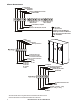
Upflow Chilled Water Cooling Units On upflow cooling units the supply and return pipes and power cables can be introduced from either the left or right side through openings in the side wall. The actual connection points are on the right side. Right Side Connections Left Side Connections 60 60 230 (9.1) 110 (4.3) L7 L5 L3 L1 R1 R3 R5 R7 L8 L6 L4 L2 R2 R4 R6 R8 230 (9.1) 110 (4.3) 0 210 (8.3) 210 (8.3) 405 (15.9) 525 (20.7) 680 (26.8) 365 (14.4) 485 (19.1) 680 (26.
na3051a Refrigerant Piping Dimensions in mm (in). Model PA211 1 circuit PA311 1 circuit PA452 2 circuits PA612 2 circuits PA862 2 circuits Pressure Line 16 mm (5/8 in) 22 mm (7/8 in) 16 mm(5/8 in) 22 mm (7/8 in) 22 mm (7/8 in) Liquid Line 12 mm (1/2 in) 16 mm (5/8 in) 22 mm (7/8 in) 16 mm (5/8 in) 16 mm (5/8 in) Considerations The refrigerant connections are located near the compressor and are labelled pressure pipe and liquid pipe.
InRoom Guide Specifications PART 1 GENERAL 1.01 SUMMARY A. The InRoom environmental control system shall be designed specifically for precision temperature and humidity control applications. It will automatically monitor and control heating, cooling, humidifying, dehumidifying, and filtering functions for the conditioned space.
PART 2 PRODUCT 2.01 STANDARD COMPONENTS A. CABINET CONSTRUCTION 1. Exterior panels: Shall be 16 gauge steel sheet metal for maximum strength. All exterior panels and frame are powder coated for durability. Front panels shall have removable hinges with a locking handle. The side panels are double wall construction with insulation between. Interior panel wall shall be insulated with 1/2 in (1.5 lb) density fiber insulation.
D. CONTROLLER 1. Controller: Shall be standard on each unit and provide precision control for the demanding requirements of Mission Critical Environments. 2. Monitoring and Configuration: The display shall allow monitoring and configuration of the precision air conditioning unit through a menu-based control. Functions include status reporting, setup, and temperature and humidity set points. Three LEDs report the operational status of the connected precision air conditioning unit. 3.
E. ELECTRICAL PANEL 1. The control voltage shall be 24 VAC, class 2 circuit. The electrical panel shall contain contactors, starters, overload protection devices, and input power disconnects. The panel shall be located in the front of the unit for available access. F. EVAPORATOR COIL/CONDENSATE PAN 1. The evaporator coil shall use aluminum fins and rifle-bored copper tubes. The coil endsupports shall be galvanized steel.
N. ADDITIONAL PROGRAMMABLE INPUT/OUTPUT (I/O) 1. The heart of the control system is the I/O controller on which up to 4 EAIO/EDIO boards shall be connected for additional inputs and outputs. The InRoom Controller Manual has a detailed description of inputs and outputs for InRoom configuration. A-In A-Out D-In D-Out IOC Board 5 4 11 7 EAIO Board 4 4 1 1 EDIO Board 1 1 8 6 O. EVAPORATOR FREEZE PROTECTION 1.
2.02 OPTIONAL COMPONENTS A. FLOORSTAND 1. The heavy gauge floor stand shall raise the unit above the subfloor to match the height of the raised floor. Heights are available from 254 mm (10 in) to 610 mm (24 in) with 76 mm (3 in) increments and shall be adjustable +/- 1.5 in. Adjustment is provided by threaded pedestals. Vibration-absorbing pads shall be included with all floorstands and are recommended with every installation. 2.
H. SECONDARY POWER SUPPLY 1. 50 Hz cooling units shall have a secondary power supply option that is controlled automatically to switch from a main power supply to a secondary power source in the event of a power outage using a digital electronic controller. 2. 50 Hz cooling units shall have a secondary power supply option that is controlled manually.
PART 3 INDIVIDUAL SYSTEMS 3.01 AIR-COOLED A. The indoor unit shall consist of an evaporator section including evaporator coil, EC fan package, controls, electrical section, and compressor. 3.02 CONDENSER A. Outdoor Propeller Fan Condenser (60Hz): The outdoor condenser cabinet shall be constructed of 2 mm (0.08 in) aluminum, with heavy gauge galvanized steel support legs. The condenser cabinet shall house the condenser coil, fan(s), fan guard(s), and condenser motor control and enabling box.
3.03 WATER-COOLED A. The water-cooled system shall consist of an evaporator section including evaporator coil, EC Fan package, controls, electrical section, compressor, and water-cooled condenser. The condenser shall be stainless steel brazed plate design and shall be controlled by 2- or 3-way valve. Maximum water pressure shall be 2758 kPa (400 psig). 3.04 GLYCOL-COOLED A.
3.09 FLUID COOLER A. Outdoor Fluid Cooler: The fluid cooler casing shall be of aluminum, and all structural supports, coil frame, motor-drive supports, and mounting legs shall be made of galvanized steel. The fluid cooler coil shall have copper tubes expanded into aluminum fins. Headers and connections shall be copper. The coil shall be pressure-tested and sealed for shipment. The fluid cooler motors shall have permanently lubricated, sealed, ball bearings, and internal overload protection.
Warranty One-Year Factory Warranty The limited warranty provided by American Power Conversion (APC®) in this Statement of Limited Factory Warranty applies only to products you purchase for your commercial or industrial use in the ordinary course of your business. Terms of warranty American Power Conversion warrants its products to be free from defects in materials and workmanship for a period of one year from the date of purchase.
IN NO EVENT SHALL APC, ITS OFFICERS, DIRECTORS, AFFILIATES OR EMPLOYEES BE LIABLE FOR ANY FORM OF INDIRECT, SPECIAL, CONSEQUENTIAL OR PUNITIVE DAMAGES, ARISING OUT OF THE USE, SERVICE OR INSTALLATION, OF THE PRODUCTS, WHETHER SUCH DAMAGES ARISE IN CONTRACT OR TORT, IRRESPECTIVE OF FAULT, NEGLIGENCE OR STRICT LIABILITY OR WHETHER APC HAS BEEN ADVISED IN ADVANCE OF THE POSSIBILITY OF SUCH DAMAGES.
Warranty Procedures Claims To obtain service under the warranty, contact APC Customer Support (see the back cover of this manual for contact information). You will need the model number of the Product, the serial number, and the date purchased. A technician will also ask you to describe the problem. If it is determined that the Product will need to be returned to APC, you must obtain a returned material authorization (RMA) number from APC Customer Support.
APC Worldwide Customer Support Customer support for this or any other APC product is available at no charge in any of the following ways: • Visit the APC Web site to access documents in the APC Knowledge Base and to submit customer support requests. – www.apc.com (Corporate Headquarters) Connect to localized APC Web sites for specific countries, each of which provides customer support information. – www.apc.com/support/ Global support searching APC Knowledge Base and using e-support.