Operating Instructions InRoom Controller for DX 21-86 and CW 40-150
Contents 1. Presentation of the system ........................................................................................5 2. Hardware components ...............................................................................................6 2.1 I/O controller ......................................................................................................................................6 2.1.1 Board design .........................................................................................
This manual is based on the software versions IOC-V2.23 and AT-V0.90.
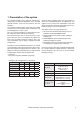
1. Presentation of the system The InRoom Controller offers maximum possible operating safety for industrial applications and a versatile operator interface. There are two interfaces with one controller. The InRoom Controller works by having each cooling unit possess its own controller while all controllers can be linked together in a bus system. This way a natural redundancy is obtained that causes the system to function with the least expense. The second interface can be accessed using a computer.
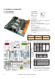
2. Hardware components 2.1 I/O controller Technical Data: 2.1.1 Board design Voltage supply: Power consumption: Fuse: Operating temp.: Storage temp.: 24(+15%) VAC 9.6 VA 2 A time-lag 5°C...40°C -30°C...60°C Onboard LEDs The function of the digital inputs is displayed by green LEDs: ON: Voltage present OFF: No voltage (alarm, failure) The function of the digital outputs is displayed by red LEDs: ON: Relay active OFF: Relay passive The OK-LED displays the I²C-bus clock.
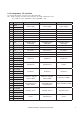
2.1.2 Assignment - I/O controller The assignment depends on the unit version (DX1, DX2, CW). DX1 - Single refrigerant circuit. DX2 - Dual refrigerant circuit. CW - Chilled water circuit. E.g.
Assignment - I/O controller (continued) Pin Designation DX2 CW Active sensor 1 Active sensor 1 Active sensor 1 36 +15V 37 GND 38 Ain 1 Room/return air temp. Room/return air temp. Room/return air temp.
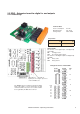
2.2 EDIO - Extension board for digital in- and outputs 2.2.1 Board design Technical Data: Power consumption: Operating temp.: Storage temp.: 10.1 VA 5°C...40°C -30°C...
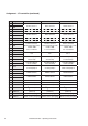
2.2.2 Assignment - EDIO1 The assignment depends on the unit version (DX1, DX2, CW). For more information, see „2.1.2 Assignment - I/O Controller“ on page 7. Pin Designation DX1 DX2 CW 1 Din 12 UPS UPS UPS 2 Din 13 Pump 1 failure Pump 1 failure Free 3 Din 14 Pump 2 failure Pump 2 failure Pump 2 failure 4 Din 15 Drycooler failure Drycooler failure Free 5 Din 16 CW disable/DX enable or Ext. alarm 3 CW disable/DX enable or Ext. alarm 1 Ext. alarm 3 6 Din 17 Ext. alarm 4 Ext.
2.2.3 Assignment - EDIO2 The assignment depends on the unit version (DX1, DX2, CW). For more information, see „2.1.2 Assignment - I/O Controller“ on page 7. Pin Designation DX1 DX2 CW 1 Din 20 Free Ext.
2.3 EAIO - Extension board for analogous in- and outputs 2.3.1 Board design Technical Data: Power consumption: Operating temp.: Storage temp.: 10.1 VA 5°C...40°C -30°C...60°C Pin position 1 10 21 30 11 20 31 40 The EAIO-board is an extension board for analogous inputs and outputs. It can be attached to the I/O controller board at any of the four sockets and will be recognized by the IOC due to a self test.
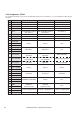
2.3.2 Assignment - EAIO The assignment depends on the unit version (DX1, DX2, CW). For more information, see „2.1.2 Assignment - I/O Controller“ on page 7.
2.4 EBUS - Extension board for 2x RS485 bus 2.4.1 Board design Technical Data: Power consumption: Operating temp.: Storage temp.: 11.3 VA 5°C...40°C -30°C...60°C JP1 Port 2 Port 3 JP2 2.4.2 Assignment - EBUS Termination jumper 14 Pin Designation 1 Port 2-H 2 Port 2-L 1 Port 3-H 2 Port 3-L X10 SUB-D 15 Function RS485 BMS-bus Jp n° Function in position 1-2 1 EBUS Port 2 termination 2 EBUS Port 3 termination RS485 Aux-bus (e.g.
2.5 InRoom Controller Board 2.5.1 Board design RS232 - service port (SUB-D 9) Technical Data: Dimensions: Voltage supply: Power consumption: Fuse: Operating temp.: Storage temp.: 270 x 110 x 40 mm 24(+15%) VAC 14 VA 2 A time-lag 5°C...40°C -30°C...60°C Position RS485 Driver for the BMS bus B Jumper X2: bus termination for RS 485 I/O-bus A Pos. A: set, Pos. B: not set Jumper X3: bus termination for RS 485 BMS-bus Pos. A: set, Pos.
3. Operator interface 3.1 I/O Controller A keyboard is used to operate the I/O controller by using specified commands that follow an easily understood syntax. To establish the connection from a PC to the IOC a 9-line cable with SUB-D 9 connectors at both ends (crossed type), which can be obtained as an option, is needed. A terminal program is also needed. You can download the terminal program "Service" from the APC website www.apc.com.
Now the bus commands in detail: - The invite command plus bus I.D. adds a bus participant. - The del command plus bus I.D. excludes the participant from the bus and sends the new I/O-bus configuration to all participants. - The checkbus command checks every I.D. address from 00 to 31 for the presence of a bus participant and updates the stored bus configuration accordingly. - The spreadbusconf command distributes the bus configuration to all participants.
3.2 Operational elements of the InRoom Controller Audible indicator <> = Selector key Ok = Confirmation key Reset = Reset key LED = Alarm LED = On/off = On/off key Display Selector key Selects menus and changes parameters. Confirmation key Acitvates the functions/parameters selected with the selector key. Reset key Press once to silence the alarm tone. Press a second time to clear the alarm message (if the cause has been eliminated). LED alarm Lights up in the event of an alarm.
4. Bus communication The maximum configuration consists of 16 cooling units with an I/O controller and an InRoom Controller. One of the features of the controller is its facility for bus operation. All that is needed is a shielded cable with two lines twisted in pairs, which are connected from unit to unit at the terminals 56-59 of each I/O controller (IOC). In the example below the bus termination of the two units that form the end of the bus (IOC 01 and IOC 17) must be enabled.
4.1 Bus with InRoom Controller + IOC Configuration of the bus participants 1. Configure the address of the bus participants with the DIP-switches or in the global status line at the InRoom Controller. 2. Declare the bus participants; there are 3 ways to do this: a. Move DIP-switch 6 from ON to OFF. b. Use the selector key to mark all units from an InRoom Controller when the bus with ID 31 is marked. Press the confirmation key OK and enter the Service password. c.
5. Controller start After having switched on the power supply of the InRoom Controller the window illustrated at the right will appear. This window displays the maximum number of 32 bus participants (bus ID 0-31). An I/O controller is displayed by a square frame containing the local temperature and humidity. A gray frame signifies that the unit is in a stop state, and a black frame indicates that the unit is in operation.
Select the InRoom Controller for further adjustments to receive the following display with the menu structure shown below. 1. In the BMS menu the global address of the InRoom Controller can be adjusted as well as an available interface that can be either RS232 or RS485. The protocol according to the BMS requirement can be adjusted here as well. 3. In the system menu, the alarm buzzer can be turned on (-1-) or off (-0-) and its pitch can be adjusted by selecting Buzzertone. Select Temp.
If you select an I/O controller the main menu will display as illustrated to the lower right with the option to choose one of the three submenus "Info", "Control" or "Service". This menu screen displays the control type (Room or Supply air) and the corresponding actual values of the control type. Below the actual values is a symbol that indicates whether the unit operates during the day or night. Day operation corresponds to operation at the first setpoint temperature.
Passwords To access the Control level and the Service level a password is required. There are four passwords total, a user-specific password for both the Control- and Service level and a master password for each level. The default user-specific password is „0000“ for both levels. It can be modified. The master passwords are for service staff only and give them authorization to adjust the bus-ID and to execute the checkbus function at the InRoom Controller.
6. Operation 6.1 Info level 6.1.1 Info commands Generally each component- or cooling unit-command that is entered without parameters only displays information without changing adjustments. However, the following commands give a general overview about the unit state and configuration. equip state is 1 is 2 is 3 - Shows the components and their numbers and the extension cards (digital/analogous). Shows the unit and functional (cooling, heating etc.) runtimes and the unit/component state.
6.1.
A B InRoom Controller - Operating Instructions 27
Display Data logger Info Use the data logger to save measured values or average values (zone data) calculated by the controller and have these values displayed in the shape of a graphical curve so as to show their time course. Values of two different sensors can be simultaneously recorded. You set the lapse of time which will be displayed. Further parameters (type of measured value and cycle) can be adjusted in the service menu.
Display Info Current values This window shows the actual values of the connected sensors the same as the setpoints adjusted at the controller. The setpoints shifted by the controller (CORR.) are also displayed. These setpoints are due to the week cycle program (see page 72) or by the sensor limitation control (see page 69). The shifted setpoints are priority setpoints. Here you can see the measured values for the zone.
Display Module state Info InRoom Controller gives a detailed representation of the operating states of the components. In the following windows you can see the operating state of each component: -0- means component is off. -1- means component is on. xxx means component does not exist. This window displays the opening degree of the valves in a percentage from 0 to 100. If your cooling unit is equipped with a heater, the operating state is displayed in this window.
Display Info Runtimes The runtimes of the listed components are shown in hours in the following windows at the bottom of the page. The functional runtimes in detail: The unit runtime comprises all times when at least one component is operating. The stoptime is counted when the unit is in local stop or timer stop or remote stop or bms-stop. The cooling runtime is counted each time that cooling is requested. The heating runtime is counted each time that heating is requested.
6.2 Control level 6.2.1 Overview structure Due to limited space within the manual, it is not possible to display entire menu branches of the two different operator interfaces on one page. We therefore applicated a city map screen on the Control and Service menu overview, consisting of columns and rows which serve to easily relocate single submenus within the overview. The columns for the Control menu are named from A to F, the columns for the Service menu from K to V.
6.2.2 Control commands A typical control command is structured as follows: top command sub-command drycool 1 startsum 32.0 command component parameter number designation parameter value Following a summary of the most frequent sub-commands: type 1/2/3..
A1B C 6.2.
53 D1E F 53 2 3 4 5 6 7 53 1 44 E-heating 2 E-heating 3 E-heating 4 2 45 3 48 49 Fan 2 54 Fan 3 52 Louver 2 Louver 3 Humidifier 2 Humidifier 3 44 44 4 52 InRoom Controller - Operating Instructions 35
Display A1 Setpoint & Limit Values Control The first two items of the control menu concern the adjustment of setpoints and limit values. The limit values are decisive for the alarms "temp/humidity too high/low". Two temperature setpoints can be adjusted, setpoint 1 concerns the operation by day, whereas setpoint 2 concerns operation at night according to the week timer (page 72). The limit values for the room air sensor, the supply air sensor, and the water sensor are displayed.
Display Cooling A2 Comp. Compressor (part 1) Control ➋a ➊a ON OFF T/°C setpoint ➊ ➋ The start temperature for the compressor is entered as a positive difference to the setpoint. Two different start temperatures + hysteresis for summer and winter operation can be entered. (➊,➊a,➋,➋a) The compressor pause is entered in seconds and serves to increase the service life of the compressor by delaying the restart by the adjusted value.
Display Cooling A2 Control Compressor (part 2) The low pressure alarm can be managed in a way to avoid a premature and unnecessary service intervention. If the LP switch releases, the compressor is stopped and restarted after the compressor pause has elapsed. The LP alarm is inhibited during the winter start delay (see page 70). This way the controller tries to bypass temporary LP alarms.
Display Valves A3 Control Suction valve The start temperature for the suction valve is entered as a positive difference to the room temperature setpoint. ➊ You can adjust a gradient, which determines the temperature range in which the valve opening increases from 0 to 100%.➋ The graphics A-C show, for a DX2-unit, how you obtain a double proportional control range by approaching the stop point of the 2nd compressor to the start point of the suction valve. Graphic A Cool. cap.
Display Valves A4 Dehumidification range min 5 GE-CW valve Control max 10 14 GE-off 20 24 °C water temp. On the InRoom Controller you can adjust the water temperature limits for dehumidification here. However, this is also possible in the dehumidification menu. Graphic A "close at comp = 0" setpoint "close at comp = 1" setpoint comp. lve va GE ➋ ➊ 200% 100% Graphic B comp.
Display A5 Valves Control G-valve The pressure setpoint is entered in the 2nd line and relates to the refrigerant condensation pressure in the condenser. ➊ The pre-start serves to provide a sufficient flow for the heat absorbing medium and to pre-cool the heat absorbing medium. When compressor operation is requested, the G-valve opens and the compressor start is delayed by the pre-start time. ➋ The pre-open value is the G-valve opening which should be obtained during the prestart time.
Display Cooling A6 Drycooler Control The start temperature for the drycooler is entered as an absolute value for the water temperature. Two different start temperatures for summer and winter operation + hysteresis can be entered. ➊,➋,➌ Note: The summer/winter operation depends on the setting in the menu Service/General settings/control/parameters. (see page 70) Drycooler ➌ ➌ ON OFF ➊ ➋ winter operation summer operation T/°C water temp.
Display Cooling A7 Pump Control Depending on which pump type you have configured, different parameters are decisive. (See table 1). The start temperature for the pump is entered as a positive difference to the room temperature setpoint. ➊ The corresponding hysteresis for the pump stop is only valid for pumps with on/off-control such as the glycol pump.➋ For speed controlled pumps you can adjust a gradient, which determines the range in which the pump speed increases from 0 to 100%.
Heating Display F3 F5 F6 Control On/Off-control Heating ➋ ON OFF setpoint T/°C ➊ E-heating/Hotgas reheat/Hot water reheat Illustration 1 Depending on which heating type you have configured, different parameters are decisive. The start temperature for every heating type is entered as a negative difference to the room temperature setpoint. ➊ The hysteresis for the heating stop is only valid for heatings with on/off-control.
Display Humidification E4 Humidifier Control On/Off-control (type 1) Humidifier ➋ ON OFF %r.h. setpoint ➊ Depending on which humidifier type you have, different parameters are decisive. The start humidity for every humidifier is entered as a negative difference to the room humidity setpoint. ➊ The hysteresis for the humidifier stop is only valid for humidifiers with on/off-control.
Display Humidification E6 Control Dehumidification (Part 1) The start humidity for dehumidification is entered as a positive difference to the room humidity setpoint. ➊ The hysteresis for the dehumidification stop is entered in the 2nd line.➋ To avoid a feedback circle of dehumidification and cooling, you can adjust a stop temperature, which is entered as a negative difference to the air temperature setpoint.
Dehumidification (Part 2) There two ways of achieving dehumidification: 1. By reducing the fan speed, this is the only way of dehumidification for CW-units. 2. By shutting down a part of the evaporator with a solenoid valve. Dehumidification type is chosen by the controller according to the following conditions: Fan speed reduction or compressor operation with a dehumidification valve present. The two dehumidification types can never be applied simultaneously. (See table 2.) Table 2 Fan speed reduction Dehum.
Display Air D5 Control Fan (Part 1) The maximum fan speed can be set in accordance to the calculated required airflow. ➊➋ For the distinction DX/CW see the overnext page.* The start temperature is entered as a negative difference to the air temperature setpoint. ➌ The start fan speed is entered as a percentage of reduction from the maximum Fan speed speed.
Air Display D6 Control Fan start phase 100% nmax ➊ ➋ fan start control start t/sec compon. start* Fan (Part 2) With the parameter "START 100%" ➊ you adjust a time which must elapse before the control begins. This way an airflow alarm is avoided which could occur due to the fan inertia. During this time the fan is operated with 100% speed.
Fan (Part 3) - Calculating the fan speed Cooling priority 1 (CW) 2 (DX) Are the conditions for a malfunction changeover met for DualFluid-units ? Are the conditions for a malfunction changeover met for DualFluid-units ? Y N CW standby management enabled? N N nmax DX Parametersetting: Y nmax CW The following decision processes are used by the controller for the fan speed calculation.
Display Air D6 Control Fan (Part 4) The "DEHUM.SPEED" ➊ is entered as a negative difference in % to the maximum speed. This is the fan speed for the first option of dehumidification. The "UPS SPEED" ➋ is also entered as a negative difference in % to the maximum speed. When the controller receives a UPS signal the controller will apply this reduced speed for an emergency operation. The parameters: - control cycle ➌ - max.
Display D7 Air Louver Control The pre-start serves to open the louver before the fan operation starts. This way a fan operation against a closed louver is avoided. ➊ Function C6 F7 Sensor In combination with these alarms a common alarm can be released. ➊➍ The alarm delay for the limit alarm ➋ and for the sensor failure alarm ➎ is entered in seconds. The limit value alarms ➌ can be assigned to an alarm relay as the sensor failure alarm ➏.
Display D1 Zone Control The parameters: - Start temperature ➊ - Hysteresis ➋ are only necessary for the GE2p-control, which is explained in a separate manual. AT-Preferences E1 The acoustic signal which resounds in the case of an alarm and the beep for pressing a key can be switched off (0=off, 1= on). The pitch of the buzzertone can be adjusted as desired. Further on you can adjust the temperature display in °C or °F ➊. The operator language ➋ can also be selected.
K1L M 6.3 Service level 6.3.
1 62 N1O P 2 E-heating 2 E-heating 3 62 62 3 63 2 3 4 5 6 7 64 Humidifier 2 Humidifier 3 63 Fan 2 Fan 3 64 Louver 2 Louver 3 5 66 4 65 66 67 66 InRoom Controller - Operating Instructions 55
Q1R S 2 3 4 5 6 7 68 73 73 7477 69 79 70 79 78 78 78 56 etc.
T 1U V 89 80 80 80 2 3 4 5 6 7 80 80 80 80 80 80 InRoom Controller - Operating Instructions 57
Display Cooling K2 Service Compressor In the first line you add the compressor to the configuration by entering "1". With "0" you disable the compressor although all settings concerning the compressor are kept. ➊ You can determine a digital output for the compressor on/off signal. ➋ The digital input for the compressor alarm can be assigned in the third line. ➌ The digital input for the low pressure alarm can be assigned in the fourth line. ➍ The compressor runtime can be adjusted in the last line.
Display K3 Valves GE-CW valve Service In the first line you add the suction valve to the configuration by entering "1". With "0" you disable the suction valve. ➊ With the parameter "A-OUT" you adjust the analogous output of the proportional signal for the suction valve. ➋ GE/CW-valve K4 In the first line you add the GE/CW-valve to the configuration by entering "1". With "0" you disable the GE/CW valve.
Display Cooling K6 Service Drycooler In the first line you add the drycooler to the configuration by entering "1". With "0" you disable the drycooler. ➊ With the parameter "D-OUT" you determine a digital output for the drycooler on/off signal. ➋ The digital input for the drycooler alarm can be assigned by the "D-IN" parameter. ➌ The drycooler runtime can be set in the last line.
Display Cooling K7 Service Pumps By setting the parameter "ACTIVE" on 1 you add a pump to the configuration. With "0" you disable the pump. ➊ In the next line you determine which type the pump shall belong to (1 = G-pump, which pumps the medium through the condenser in a GE2-unit, 2 = GE-pump, which pumps the medium through the free cooling coil in a GE2-unit, 3 = Glycol-pump - all pumps for G-, GE1 units which are located outside the cooling unit).
Display N1 Heating E-heating/Hotgas reheat/Hot water reheat Service Setting the parameter ACTIVE to 1 adds a reheat to the configuration. Setting this parameter to 0 disables the reheat. ➊ In the next line you determine the reheat type (1: reheat with on/off control, 2: reheat with proportional control). ➋ With the parameter "D-OUT" you determine a digital output for the reheat.
Display Humidification O1 Service Humidifier Setting the parameter ACTIVE to 1 adds a humidifier to the configuration. Setting this parameter to 0 disables the humidifier. ➊ In the next line you determine the humidifier type (1: humidifier with on/off control, 2: humidifier with proportional control). ➋ With the parameter "D-OUT" you determine a digital output for an on/off humidifier. ➌ With the parameter "A-OUT" you adjust the analogous output of the proportional signal for a humidifier.
Display Air P1 Fan Service Setting the parameter ACTIVE to 1 adds a fan to the configuration. Setting this parameter to 0 disables the fan. ➊ In the next line you determine the fan type (1: fan with on/off control, 2: EC-fan with proportional speed control). ➋ With the parameter "D-OUT" you determine a digital output for an on/off fan. ➌ With the parameter "A-OUT" you adjust the analogous output of the proportional signal for a speed controlled fan.
Display Equipment N6 Sensor Service PURPOSE: 1 - Room temperature 2 - Room humidity 3 - Supply temperature 4 - Supply humidity 5 - Water temperature 1 6 - Outside temperature 7 - Outside humidity 8 - Condensation temperature 1 9 - Condensation pressure 1 10 - Evaporation temperature 1 11 - Evaporation pressure 1 12 - Water temperature 2 13 - Condensation temperature 2 14 - Condensation pressure 2 15 - Evaporation temperature 2 16 - Evaporation pressure 2 17 - Setpoint temperature 18 - Setpoint humidity
Display O5 Equipment Aux. Ports/Aux. Ports Service You can adjust digital in- and outputs for non-component-related alarms or messages in this window. In detail you can adjust the digital output for the common alarm ➊ and for the wintermode ➋. The wintermode signal can be forwarded to a BMS system. You can also adjust the digital inputs for the remote contact ➌, the fire alarm ➍ and the water detector ➎, which creates the water alarm and for the UPS operation ➏.
Display Equipment P6 Aux. Ports/Aux. Alarm Service In the first line you can type in the alarm text which you want to be displayed in case of the alarm. ➊ By setting the parameter "ACTIVE" on 1 you add an external alarm to the configuration. With "0" you disable the ext. alarm. ➋ With the parameter "D-IN" you adjust the digital input for the alarm signal. ➌ You can adjust, whether the external alarm releases a common alarm (0= no, 1 = yes).
Gen. settings Display R2 Service Control Here you can choose the control type. The display of the actual values changes corresponding to the above adjusted type of control (Room / Sup.Air). ➊ The room air control is the standard control. The temperature/humidity sensor is placed in the return air intake and the InRoom Controller controls in accordance with the setpoints set in the "Control/temperature/humidity" menu. The limit values of room air are monitored.
Display Gen. settings R2, R3 Service Setpoint Room air sensor T/°C Temperature 20,5 20 14 15 16 17 T/°C Actual value Supply air sensor Example (temperature): 20.5 = 20 + 0.5 • (16 - 15) Setpoint Supply air sensor T/°C Temperature 18 17,5 21 22 23 24 T/°C Actual value Room air sensor Example: 17.5 = 18 + 0.
Display Gen. settings R3 Control/Parameters (Part 2) Service The controller has the option of starting a stand-by unit after an adjustable positive temperature difference to the air temperature setpoint is achieved. This difference can be adjusted by the parameter "Loadstart" ➏ . The adjustment 0.0K disables this function. The sequencing function is not influenced by starting a standby-unit.
Gen. setting Control/Parameter (Part 3) Cooling priority The cooling priority determines the overriding cooling circuit for units with two different cooling systems. The parameters 0, 1, and 2 can be adjusted. 0 - no priority, this is the adjustment for GE-systems, where a mixed operation of both systems is possible. 1 - CW- means that chilled water cooling has priority at ACW/GCW-units. 2 - DX- means that compressor cooling has priority at ACW/GCW-units.
Day & Night Display Service The week timer is based upon two different temperature setpoints which you have already adjusted in the control/temperature menu. Setpoint 1 is represented by a thick line, setpoint 2 by a dotted line. For each hour of each day of the week you choose among three settings: Display in the main menu when the timer program is executed: Display: 1. Cooling unit off 0 2. Cooling unit on with setpoint 1 1 3.
Display Gen. settings Q3 Service UPS You can define the air conditioning functions for operation with an Uninterrupted Power Supply. If the controller receives the signal at its digital input for UPS operation, all the functions which are enabled by "1" will be admitted, whereas the functions with a "0" will be disabled. Note that also the fan speed will be reduced to a pre-adjusted value in case of UPS-operation. See page 51. Interfaces Q4 The global address can be adjusted in a range from 1 to 255.
Display Gen. settings Q5 Sequencing Service The zone concept is based on the idea to obtain a homogeneous room climate within a determined space by distributed generation of conditioned air. Within a zone only one room temperature exists, which is calculated as the average value of all connected room temperature sensors of the units in operation; this also applies to the room humidity, supply temperature, and supply humidity.
Failure dependent change-over Definition of valid alarms for one zone For each zone any number out of 26 alarms in total can be defined as valid alarms. If such an alarm occurs the corresponding unit is switched off and notified as defective. All 26 alarms are defined as valid alarms by default. The alarm "unit not available" can not be deleted from the alarm list. This alarm is always part of the valid alarms and appears due to a bus failure or when the unit has locally been switched off.
Example for a Sequencing configuration: The zone shown on the right is to be configured. - All alarms shall remain valid. - The number of defective units shall be 3. - The emergency temperature shall be 17°C. - The sequencing cycle shall be 5 hours. Zone 01 Stand -by Unit 01 Unit 03 Unit 07 1. Determinating the standby units in the general overview Select the units one by one and set the operating status by means of the ON/OFF switch at the InRoom Controller.
Display Q5 Service 2. CW Standby Management The CW standby management can be carried out with CW units and Dualfluid units with CW cooling priority. The basic idea is to share the heat load permanently with as many units as possible in order to reduce the fan speed of all units and thus to save energy. As a result, the provided standby units must constantly take part in the cooling process.
Display R5-R7 Data Service Runtime Being an exact copy of the same submenu in the Info menu, the Service Runtime menus provide the possibility to reset the runtimes. The corresponding commands: ➊ ➋ ➌ ➍ ➎ ➏ comp 1 runtime 0 fan 1 runtime 0 eheat 1 runtime 0 pump 1 runtime 0 humi 1 runtime 0 drycool 1 runtime 0 Times are entered in hours. The numbered callouts refer to the corresponding passages in the descriptive text.
Data Display S3 Service Data logger Here you can adjust the basic conditions for the data logger. You can adjust sensor type ➊ and cycle ➋, the interval in which measured values of the corresponding sensor are stored. Each data logger can store a maximum of 1440 datapoints. The 1441 datapoint deletes the first datapoint, the 1442 datapoint deletes the second datapoint, etc.. If you adjust a cycle of 1 minute you obtain a graphic for a lapse of time of 1440 minutes, which corresponds exactly to 24 hours.
Display U2-U5 Manual Operation Service The manual operation menu consists of two columns of parameters which are needed for the operation. In the first column (titled EN.) you enable the manual operation of the listed component by setting the parameter to "1". ➊ The second column (titled STATE) displays the actual state of the component. After you have enabled the manual operation in the first column, you can switch on/off the component itself.
6.4 Default configurations Unit parameters Range Value System name 20 characters System name Unit name 20 characters Unit name 0 - 31 13 Unit ID Global address 0 - 32767 1 Local stop 0-1 1 Monitoring stop 0-1 0 Sequencing stop 0-1 0 1 PT language 0: English 1: German Temperature unit 0: °C 1: °F 0 Temperature setpoint 5 - 35 24°C Temperature setpoint, night 5 - 35 27°C Humidity setpoint 5 - 90 45% r. h.
Zone parameters Range Value Zone 1 - 32 0 0 - 65535 0h Sequencing time Test sequencing 0-1 0 Valid alarms 1 - 26 all valid Number of defective units 0 - 32 0 Emergency temperature 0 - 40 16°C 60 - 100 85% 0-1 0 Zone fan speed nMax CW standby management The parameter "zone" is not a zone parameter but can be adjusted separately for each unit. Due to its context it is displayed in this table.
Components Compressor Range Compressor 1 Compressor 2 Summer start 0 - 9.9 0.4 K 0.6 K Summer hysteresis 0 - 9.0 0.7 K 0.7 K Winter start 0 - 9.9 0.7 K 0.9 K Winter hysteresis 0 - 9.0 0.7 K 0.
Drycooler Range Drycooler 1 Drycooler 2 Drycooler 3 Drycooler 4 Winter start 5 - 35 10°C 11°C 12°C 13°C Summer start 10 - 50 34°C 35°C 36°C 37°C Stop hysteresis 1 - 9,9 2K 2K 2K 2K Component configured 0 -1 0 0 0 0 Output D 0 - 31 9 10 17 18 Alarm input D 0 - 43 15 15 15 15 Alarm priority 0 - 31 0 0 0 0 Common alarm 0-1 0 0 0 0 Alarm delay 0 - 100 5s 5s 5s 5s Pre-open time 0 - 20 10 s 0s 0s 0s 50 - 100 100% 0% 0% 0% Preliminary speed Contr
Reheats Range electr. reheat 1 electr. reheat 2 electr. reheat. 3 electr. reheat 4 Type 1-2 1 1 1 1 Start 0 - 9.9 1.5 K 2K 2.5 K 3K Stop hysteresis 0 - 9.9 0.5 K 0.5 K 0.5 K 0.5 K 0.5 - 9.9 0.5 K 0.5 K 0.5 K 0.
Dehumidifier Range Dehumidifier Start 0 - 100 10 %r.h. Stop hysteresis 0 - 30 5 %r.h. Dehumidification stop 0 - 10 5K Dehumidif. valve conf. 0-1 0 Bypass valve conf. 0-1 0 Output D 0 - 31 5 min water temp. 0 - 50 5°C max water temp.
Louver Range Louver 1 Louver 2 Louver 3 Pre-start 0 - 180 90 s 90 s 90 s Output D 0 - 31 7 10 18 Component configured 0-1 0 0 0 Sensors Range Sensor 1 Sensor 2 Sensor 3 Sensor 4 Purpose 1 - 16 1 2 3 4 Input A 1 - 21 1 2 3 4 Type 1-5 1 1 1 1 Component configured 0-1 1 1 1 1 Min. measure value -50 - 100 0°C (-50 - 100) 0%r.h (0 - 100) 0°C (-50 - 100) 0%r.h (0 - 100) Max. measure value -50 - 100 50°C (-50 - 100) 100%r.h (0 - 100) 50°C (-50 - 100) 100%r.
Sensors (continued) Range Sensor 9 - 21 Purpose 1 - 16 0 Input A 1 - 21 0 Type 1-5 0 Component configured 0-1 0 Min. measure value -50 - 100 0 Max. measure value -50 - 100 0 Min. output value 0 - 20 0 Max. output value 0 - 20 0 Max. difference 0 - 100 10% Limit - alarm priority 0 - 31 0 Limit - common alarm 0-1 1 Limit - alarm delay 0 - 100 5s Failure - alarm priority 0 - 31 0 Failure -common alarm 0-1 1 0 - 100 5s -10.0 - 10.
6.4.1 Preconfigurations U1 10 default configurations for different unit cooling systems are stored in the I/O controller. Unit type DX GE1 GE2 AGCW CW 1 circuit dx1 ge11 ge21 agcw1 cw 2 circuits dx2 ge12 ge22 agcw2 cw2 The table contains the parameters for the IOCcommand. Command: loaddefault dx1 The following table displays the differences in relation to the default settings when a pre-configuration is selected.
7. Alarm treatment 7.1 Alarm display The alarm messages are displayed in the standard window of each unit with IOC. At the same time the symbol in the bottom-left corner of the window indicates that an alarm has occurred. An alarm tone proves the presence of an alarm independantly of the actual menu window of the InRoom Controller. Attention: The alarm tone can be disabled. (See page 22). Commands „state“ The alarm display in the command level is passive.
7.
7.3 Component-related alarms The table shows the main components with their standard alarm input and the possible alarms.
7.
8. Configuration notes First steps after installing new software 1. Load software on IOC, respectively on InRoom Controller. (See 8.1 Loading a new software). 2. Check bus configuration (Configuration is kept after loading the software). 3. Load a default configuration according to the unit type (See 6.4.1 pre-configurations). 4. Check the equipment using the command "equip". 5. Configure additional components. On the InRoom Controller you can do this in the Service-level in the submenus of the menu "Equipment".
8.1 Loading new Software For the control system there are two types of software. The essential control software is located in the Flash-EPROM on the IOC-board. The second software contains the menu structure and is located in the EPROM of the InRoom Controller board. The control parameters in the IOC are resistent and do not have to be re-entered after loading the software. This is also the case for the IO bus configuration of the InRoom Controller.
8.1.1 Operation of the program "InRoom-Service.exe" With an up-to-date Windows XP system the program must only be copied onto the computer hard disk and can directly be started by a doubleclick. The files (InRoom-Service.exe and IOC-Service.exe) must be stored in the same folder. With former Windows XP versions, Windows 2000, Windows ME, and Windows 98 the install-package that can be obtained from the APC website must be carried out. InRoom - Service Start InRoom-Service.
9. Network Management Card 9.1 Quick Configuration The InRoom Precision Air Conditioner is shipped with a Network Management Card that enables you to manage the air conditioner over your network. You must set up the Network Management Card to control the InRoom Precision Air Conditioner through a network. The Network Management Card comes pre-assembled to an interface board using two sets of pin connections.
APC Device IP Configuration Wizard You can use the APC Device IP Configuration Wizard at a computer running Microsoft Windows 2000, Windows 2003, or Windows XP to configure a Network Management Card. 1. Insert the Utility CD into a computer on your network and click the „Device IP Configuration Wizard“ link. 2. Launch the Device IP Configuration Wizard, when prompted, or, if prompted to restart the computer, access the Wizard from the Start menu after the computer has restarted. 3.
2. When the Network Management Card reboots, the BOOTP server provides it with the TCP/IP settings. – If you specified a bootup file name, the Network Management Card attempts to transfer that file from the BOOTP server using TFTP or FTP. The Network Management Card assumes all settings specified in the bootup file. – If you did not specify a bootup file name, the Network Management Card can be configured remotely by using the control console or the Web interface (user name and password are both apc, by default).
Remote access to the control console From any computer on the same subnet as the Network Management Card, you can use ARP and Ping to assign an IP address to a Network Management Card, and then use Telnet to access the control console of that Network Management Card and configure the needed TCP/IP settings. Note: After a Network Management Card has its IP address configured, you can use Telnet, without first using ARP and Ping, to access that Network Management Card. 1.
Control console After you log on at the control console, as described in “Remote access to the control console” on page 100: 1. Choose Network from the Control Console menu. 2. Choose TCP/IP from the Network menu. 3. If you are not using a BOOTP or DHCP server to configure the TCP/IP settings, select the Boot Mode menu. Select Manual boot mode, and then press ESC to return to the TCP/IP menu. (Changes will take effect when you log out.) 4. Set the System IP, Subnet Mask, and Default Gateway address values.
9.2 Access a Configured Unit Overview After the InRoom Precision Air Conditioner is running on your network, you can use the interfaces summarized here to access the InRoom Precision Air Conditioner. See the User’s Guide for more information on the interfaces. Web interface As your browser, you can use Microsoft® Internet Explorer 5.5 and higher (on Windows operating systems only), Firefox 1.x by Mozilla (on all operating systems), or Netscape® 7.
Telnet/SSH You can access the control console through Telnet or Secure SHell (SSH), depending on which is enabled. (An Administrator can enable these access methods in the Web interface by selecting the Administration tab, then Network on the top menu bar, and the access option under the Console heading on the left navigation menu.) By default, Telnet is enabled. Enabling SSH automatically disables Telnet. Telnet for basic access.
SNMP After you add the PowerNet® MIB to a standard SNMP MIB browser, you can use that browser for SNMP access to the InRoom Precision Air Conditioner. The default read community name is public; the default read/write community name is private. Note: If you enable SSL and SSH for their high-security authentication and encryption, disable SNMP. Allowing SNMP access to the InRoom Precision Air Conditioner compromises the high security you implement by choosing SSL and SSH.
9.3 Recover From a Lost Password To access the control console, you can use a local computer (a computer that connects to the Network Management Card or other device through the serial port). 1. Select a serial port at the local computer, and disable any service that uses that port. 2. Use the supplied configuration cable to connect the selected port to the serial port (X15) on the controller board. Electrical Hazard: Potentially dangerous and lethal voltages exist within the electrical cabinet.
APC Worldwide Customer Support Customer support for this or any other APC product is available at no charge in any of the following ways: • Visit the APC Web site to access documents in the APC Knowledge Base and to submit customer support requests. – www.apc.com (Corporate Headquarters) Connect to localized APC Web sites for specific countries, each of which provides customer support information. – www.apc.com/support/ Global support searching APC Knowledge Base and using e-support.