
Operating instructions


InRoom Controller - Operating Instructions32
A2
47
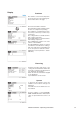
6.2 Control level
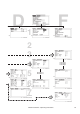
6.2.1 Overview structure
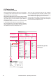
Due to limited space within the manual, it is not possib-
le to display entire menu branches of the two different
operator interfaces on one page.
We therefore applicated a city map screen on the Control
and Service menu overview, consisting of columns and
rows which serve to easily relocate single submenus
within the overview.
The columns for the Control menu are named from A to
F, the columns for the Service menu from K to V.
On each page there is one top row without a number,
which contains the top level menu and seven rows for
the submenus which are named from 1 to 7.
There are up to 4 submenu levels.The first submenu
level is horizontally located. All other submenu levels
are vertically located. The second submenu level on an
arrow indicates the beginning of a new submenu.
On the pages which follow the overview, only the pa
-
rameter menus are explained, which are normally the
menus of the lowest submenu level.
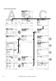
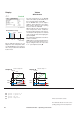
top level menu
1st submenu level
4th submenu 3rd submenu 2nd submenu
level level level
The submenus can also
continue to the right on the
following page.
sector
sector A2
page, on which
there is a detailed
menu descripti-
on