
Operating instructions


59InRoom Controller - Operating Instructions
➊
➋
➌
➍
➎
➏
K3
K4
K5
➐
➑
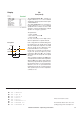
Service
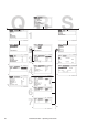
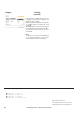
The corresponding commands:
Display Valves
GE-CW valve
In the first line you add the suction valve
to the configuration by entering "1". With
"0" you disable the suction valve. ➊
With the parameter "A-OUT" you adjust
the analogous output of the proportional
signal for the suction valve.
➋
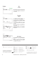
GE/CW-valve
In the first line you add the GE/CW-valve
to the configuration by entering "1". With
"0" you disable the GE/CW valve.
➌
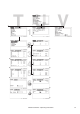
With the parameters "A-OUT 1" and "A-
OUT 2" you adjust the first and second
analogous output of the proportional
signal for the GE/CW-valve.
➍➎ Two
GE/CW-valves exist in A/C-units of the
CW2-type only.
The digital input, which receives the signal
for the commutation from output 1 to out-
put 2, can be assigned in the last line. ➏
With the reception of the signal the
alarm message "CHILLER FAILURE" is
displayed.
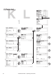
G-valve
In the first line you add the G-valve to the
configuration by entering "1". With "0" you
disable the G-valve.
➐
With the parameter "A-OUT" you adjust
the analogous output of the proportional
signal for the G-valve.
➑
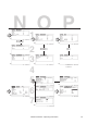
The numbered callouts refer to the corres-
ponding passages in the descriptive text.
suctionv 1 conf 1
suctionv 1 aout 3
gecwv conf 1
gecwv aout1 3
gecwv aout2 4
gecwv din 17
gvalve conf 1
gvalve aout 4