
Operating instructions


InRoom Controller - Operating Instructions94
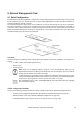
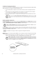
8. Configuration notes
First steps after installing new software
1. Load software on IOC, respectively on InRoom Controller. (See 8.1 Loading a new software).
2. Check bus configuration (Configuration is kept after loading the software).
3. Load a default configuration according to the unit type (See 6.4.1 pre-configurations).
4. Check the equipment using the command "equip".
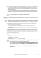
5. Configure additional components.
On the InRoom Controller you can do this in the Service-level in the submenus of the menu "Equipment". Part
of the configuration is the activation of the component, the allocation of an output for the component control,
and eventually the assignment of an alarm input.
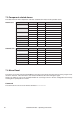
Possible maximum equipment according to unit type
Component A G GE1 GE2 ACW GCW CW CW2 max.
Louver
1 1 1 1 1 1 1 1 3
Fan
1 1 1 1 1 1 1 1 3
Compressor 1 - 2 1 - 2 1 - 2 1 - 2 1 - 2 1 - 2 2
Suction valve
1 1 1 1 1 1 2
Hotgas-Bypass 1 1 1 1 1 1 1
Dehumidification valve
1 1 1 1 1 1 1
G-valve
1 1 1 1
GE/CW-valve
1 1 1 1 1 (2)* 1
G-pump 1 1
GE-pump 1 1
Glycol pump 1 - 2 1 - 2 1 - 2 1 - 2 1 - 2 1 - 2 1 - 2 2
Drycooler
1 - 4 1 - 4 1 - 4 1 - 4 4
E-Heating 1 - 4 1 - 4 1 - 4 1 - 4 1 - 4 1 - 4 1 - 4 1 - 4 4
Hotgas reheat 1 1 1 1 1 1 1
PWW-reheat
1 1 1 1 1 1 1 1 1
Humidifier
1 - 3 1 - 3 1 - 3 1 - 3 1 - 3 1 - 3 1 - 3 1 - 3 3
Conductivity meter 1 1 1 1 1 1 1 1 1
* Only one GE/CW-valve can be configured, but 2 analogous outputs are available.
The same parameters are valid for both valves.
The following components can only be configured in a single quantity.
Hotgas-Bypass
Dehumidif. valve
G-valve
GE/CW-valve
Hotgas reheat
PWW-reheat
Conductivity meter
Further components
Component max.
Sensor 21
external alarm
10
dehumi confbypass 1
dehumi confvalve 1
gvalve conf 1
gecwv conf 1
gasheat conf 1
pwwheat conf 1
humi 1 confcon 1