User Guide InRoom SC 50 Hz ACPSC3000 MODE InRoom TEMP SC
American Power Conversion Legal Disclaimer The information presented in this manual is not warranted by the American Power Conversion Corporation to be authoritative, error free, or complete. This publication is not meant to be a substitute for a detailed operational and site specific development plan.
Contents General Information ........................................................ 1 Overview . . . . . . . . . . . . . . . . . . . . . . . . . . . . . . . . . . . . . . . . . . . . . . . . 1 Save these instructions . . . . . . . . . . . . . . . . . . . . . . . . . . . . . . . . . . . 1 About the InRoom SC Portable Cooling Unit . . . . . . . . . . . . . . . . . . 1 Performance Specifications . . . . . . . . . . . . . . . . . . . . . . . . . . . . . . . 1 Safety symbols that may be used in this manual . .
Display Interface . . . . . . . . . . . . . . . . . . . . . . . . . . . . . . . . . . . . . . . . . 14 Display Screen Information . . . . . . . . . . . . . . . . . . . . . . . . . . . . . . . 14 Function Button and Indicator Light Operation . . . . . . . . . . . . . . . 15 Remote Control. . . . . . . . . . . . . . . . . . . . . . . . . . . . . . . . . . . . . . . . . . 16 Maintenance................................................................... 19 Clean the exterior . . . . . . . . . . . . . . . . .
General Information Overview Save these instructions This manual contains important instructions that must be followed during the installation of this equipment. About the InRoom SC Portable Cooling Unit InRoom SC cooling units are portable, compact air conditioners designed for spot-cooling, emergencycooling, and after-hours cooling of server closets and data centers.
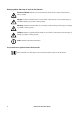
Safety symbols that may be used in this manual Electrical Hazard: Indicates an electrical hazard which, if not avoided, could result in injury or death. Danger: Indicates a hazard which, if not avoided, could result in severe personal injury or substantial damage to product or other property. Warning: Indicates a hazard which, if not avoided, could result in personal injury or damage to product or other property.
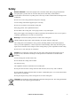
Safety Electrical Hazard: Connect the equipment to a 220-240V, 50Hz, three prong grounded outlet (two poles plus a ground). The use of a time-delay fuse or time-delay circuit breaker is recommended. Connection to any other power source may result in a shock hazard or damage to the cooling unit. Do not cut or remove the ground from the power cord plug. Use the cooling unit with the supplied power cord only. Do not use an extension cord with this cooling unit.
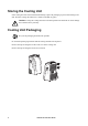
Storing the Cooling Unit If the cooling unit will not be installed immediately, replace the packaging to protect from damage and dust. Store the cooling unit indoors in a climate controlled, dry place. Caution: Leaving the cooling unit uncovered and exposed to the elements can cause damage and voids the factory warranty. Cooling Unit Packaging Recycle the packaging material when possible. Do not discard packaging material until the cooling unit has been inspected.
Inspecting the Cooling Unit Your cooling unit has been tested and inspected before shipment. To ensure that the cooling unit has not been damaged during transit, carefully inspect the cooling unit immediately upon receipt. Caution: Do not tip or place the unit on its side. Verify that all parts ordered were received as specified. See “Inventory” on page 6.
Tools Required Phillips head screwdriver Inventory MODE TIMER SEND DRY FAN SLEEP Hr. - °C + °C Min ON/OFF MODE InRoom SC na3368a TEMP 6 Item Description Item Description 1 Cooling unit 7 Wrench (for casters) 2 Remote control 8 Drain hose 3 Ceiling adapter 9 Phillips head screw, ST4.2 x 9.5 (for hose clip) 4 Exhaust cap Exhaust hose : Hose Clip 5 Phillips head screw ST4.2 x 9.
Component Identification ACPSC3000 MODE TE MP SC om In Ro SC InRoom TEMP MO DE + °F TIMER MODE FAN Min na3365a - °F SLEEP ON/OFF Hr.
Installation Location Requirements When deciding where to locate the cooling unit, consider cooling needs, air flow, and the location of the electrical outlet. The cooling unit can be no more than 2.4 m (8 ft) from the electrical outlet. MODE InRoom SC TEMP na3362b Cooling needs. Position the cooling unit as close as possible to the main heat source that requires cooling. > 500 (20) > 500 (20) Dimensions are shown in mm (in). Air flow.
Exhaust Duct Assembly Dry Mode. Exhaust air must be allowed to return to the room in order for dehumidification to take place. Do not connect the exhaust hose to vent it outside the room. Continuous drainage for the condensate drain pan must be provided or it will fill up and the unit will automatically shut down until it is emptied. Cool Mode. Exhaust air must vent outside the room when using the cool mode. Note: Leave the door to the room slightly ajar to equalize pressure to improve ventilation.
Installation. Exhaust air can be vented to the outside through the ceiling. The cooling unit should be positioned a minimum of 500 mm (20 in) from any wall; either at the back or on the sides. In a dropped ceiling, the ceiling adapter can be installed in place of one of the ceiling tiles. na3416a 1. Position the end of the exhaust hose so the small tabs line up with the holes in the ceiling adapter.
Window Installation. Exhaust air can be vented to the outside through a window. The ceiling adapter can be placed into a window opening and the window can be pulled down to hold the panel in place. Install the exhaust hose to the adapter panel as done on the previous page. Wall Installation. Exhaust air can be vented to the outside through a wall. Adhere to local restrictions and regulations.
Drain Kit Installation The InRoom SC utilizes evaporative technology, which eliminates the need for a condensate tank. To manage any excess condensation, a drain pan is located in the bottom of the unit. When the drain pan is full, a light will flash on the display and an alarm will sound to alert you. The cooling unit will automatically shut down. To avoid a shut down, install the drain kit and route the hose to a drain. See “Inventory” on page 6 for a description of the contents of the drain hose kit.
Operation Control Panel TEMP na3366a MODE InRoom SC Function Button Locations Item Function Description 1 Temp Up and down arrow buttons adjust the thermostat. 2 Display interface LCD user interface displays instructions and functions. 3 Mode selection Three mode control settings: Cool, Dehumidify, and Fan. The settings are adjusted by pressing the Mode Control Button. 4 Fan speed control Press the Fan Speed Control button to move through the three settings: Low, Medium and High.
FAN COOL SLEEP °C SET TEMP ON LOW MED HIGH AUTO SET TIME DRY na3367a Display Interface OFF Display Screen Information Item Function 14 Description 1 Sleep mode indicator Sleep mode is an undercooling mode that is used during times of nonpeak heat. Sleep mode is activated by setting the timer. The set temperature will automatically increase at intervals until the timer turns off the Sleep mode. 2 Cool mode indicator Cool mode cools the room. Temperature and fan speed are set by the user.
Function Button and Indicator Light Operation Cooling Mode. In Cool mode the unit attempts to bring the room air temperature down to the set temperature. The fan speed and temperature are adjusted in Cool mode. Note: The room temperature must be higher than the set temperature in order for the cooling mode to start. Dry Mode (Dehumidify). Press the ON/OFF button to start the cooling unit. Press the Mode button to choose Dry. In Dry mode, the fan speed is fixed to Low.
Remote Control Caution: 1. Do not drop the remote control. 2. Do not leave the remote control exposed to direct sunlight. Note: 1.To avoid interference, do not use the remote control within one meter (3 ft) of a television or other electrical appliance 2. The remote control is functional up to 7 m (23 ft) from the cooling unit. All portable cooling units are provided with a hand-held remote control.
Timer Operation. Set Timer without changing settings: Press the Timer button to show the remaining time on the display. Press the Hour button to change the adjust the delay time from 0.5 to 18 hours then press Send. If the cooling unit is ON, when the timer counts down to 0, the cooling unit will turn OFF. The remote timer cannot be set to turn the cooling unit ON. Set Timer changing settings: With the cooling unit ON, 1. - Select the mode and press Send. 2. - Select the fan speed and press Send. 3.
Battery Care The remote control requires two AAA (IEC R03) 1.5V batteries (not included). Remove the cover on the back of the remote control and insert the batteries with the (+) and (-) poles pointing in the proper direction. + - na3361b - + Caution: Use only AAA (IEC R03) 1.5V batteries. Do not use rechargeable batteries. Caution: Replace both batteries at the same time. Caution: Dispose of used batteries appropriately.
Maintenance Electrical Hazard: Before performing maintenance on the cooling unit: 1. Turn the cooling unit off. 2. Unplug the cooling unit. Warning: Damage to equipment may occur if: 1. Caustic substances are used to clean the cooling unit. 2. The unit is subjected to excess water. 2. Air filters are cleaned too aggressively or allowed to dry in direct sunlight. Clean the exterior Wipe dirt and dust from the exterior surfaces with a soft, dry cloth.
Empty the condensate drain pan If the cooling unit is not routed to a permanent drain, allowing the drain pan to drain, the unit will shut down when the drain pan is full. See “Continuous draining” on page 12 for more information. Caution: The cooling unit must be turned off and unplugged before draining. 1. With the power off and the unit unplugged, move the cooling unit to an appropriate place to drain the drain pan.
Caster replacement Warning: Tipping the cooling unit can cause damage. Raise the unit levelly at least 250 to 300 mm (10 to 12 in) to access the caster. TEMP In Ro om SC MO DE Use the wrench that was shipped with the unit. See “Inventory” on page 6. Apply the wrench to the nut at the top of the caster. Turn the nut counterclockwise to loosen. When the old caster is removed, use the wrench to attach the new caster by turning the nut at the top of the caster clockwise.
Troubleshooting Problem Solution Unit does not run If you are attempting to run the cooling unit from the remote control, check that the batteries in the remote control are good. Check that the unit is properly plugged into the power outlet. The unit stops running during operation. Check that the set temperature is lower than the room temperature. The unit runs but does not Check that the room is closed (no doors or windows cool. open). Check that no heating appliance is working nearby.
Spare Parts List Part Number Description 0J-0H-0307 Ceiling exhaust kit 0J-0H-0308 Exhaust duct kit 0J-870-16520 Swivel caster 0J-876-0317 Air filter InRoom SC 50 Hz User Guide 23
Specifications MODE TE MP SC In Ro om SC InRoom TEMP na3399a MO DE Model Net weight (Equipment only) - Kg (lb) Shipping weight - Kg (lb) Dimensions - H x D x W - mm (in) Voltage/Frequency/Phase Power input Operating current Capacity - Total kW (BTU/hr) Fuse rating: Fuse 1 Fuse 2 Dehumidifying capacity - l/h (gal/h) Condensate tray capacity Refrigerant - Kg (lb) Refrigerant Global Warming Potential (GWP) Timer Air flow volume - M3/sec (CFM) Operating Range - °C Sound Level - dB(A) with exhaust duct:
APC Worldwide Customer Support Customer support for this or any other APC product is available at no charge in any of the following ways: • Visit the APC Web site to access documents in the APC Knowledge Base and to submit customer support requests. – www.apc.com (Corporate Headquarters) Connect to localized APC Web sites for specific countries, each of which provides customer support information. – www.apc.com/support/ Global support searching APC Knowledge Base and using e-support.