Operating Instructions InRoom CW/DX - 60Hz 21 - 86kW DX 40 - 150kW CW
This manual is available in English. Dieses Handbuch ist in deutsch verfügbar. Este manual está disponible en español. Ce manuel est disponible en français. Questo manuale è disponibile in italiano. Instrukcja Obsługi w jezyku polskim jest dostepna.
Contents 1. Safety ...........................................................................................................................5 1.1 Regulations .......................................................................................................................................5 1.2 Symbols.............................................................................................................................................5 1.3 Safety instructions .....................................
8. Dismantling and disposal ........................................................................................53 9. Options ......................................................................................................................54 9.1 Steam humidifier ............................................................................................................................. 54 9.1.1 Description .............................................................................................
1. Safety 1.
1.3 Safety instructions General These operating instructions contain basic information which is to be complied with for installation, operation and maintenance. The plumber and the responsible trained staff/operators must read and comply with these instructions before assembly and commissioning. The instructions must be permanently available at the place where the system is used. R407C refrigerants are used in all units. R407C is a gaseous fluorinated hydrocarbon which is liquefied under pressure.
- Refrigerants containing FCs contribute to global warming and to climate changes. The FCs must therefore be disposed of in accordance with the regulations, i.e. only by companies specially qualified under § 191 of the water resources management law and licensed as recognized disposal companies for refrigerants. 1.
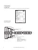
2. Description 2.1 Type code The type code represents the unit variant of your cooling unit and can be found on the rating plate. The rating plate is located in the door in front of the electrical compartment.
Option Group 1 Voltage Phase/Hertz Reheat Humidification Water Detection K A X X X X - None, A - Cable X - None, S - Steam Canister X - None, E - Electric A: 3/60 B: 208-230V B: 3/50 G: 380-415V C: 1/60 K: 460-480V D: 1/50 M: 575-600V E: 3/50 or 60 F: 1/50 or 60 Option Group 2 Refrigerant Head pressure control valve Chilled water valve Placeholder Placeholder H X 3 X X X - reserved for future use X - reserved for future use X - None, 2 - 2-way, 3 - 3-way X - None, 2 - 2-way, 3 - 3-way G: R22 H:
Unit Variants The different versions of the product range are defined by the airflow direction, the unit capacity, the number of refrigerant circuits and the cooling method. The units exist in 5 cabinet sizes with different width, to which specific features adhere as far as the heating and humidifier equipment is concerned. Size 1 2 3 4 5 The GE version differs from the other versions by larger cabinet sizes at the same capacity.
Air flow (D) A distinction is made between downflow and upflow cooling units in respect of air flow. On downflow units the room air is drawn in to the cooling units from above and passed down into the raised floor void. On upflow units the room air is drawn in from the front side of the cooling unit and passed upward. Downflow Upflow room / return air supply air room / return air supply air Number of refrigerant circuits The cooling units exist with either one or two refrigerant circuits.
A-system The air-cooled (A) direct expansion (DX) system uses refrigerant as the heat transfer medium. Room air re-circulates through the internally mounted cooling unit which houses the evaporator coil, scroll compressor and refrigeration system. A remotely mounted aircooled condenser is connected, by specialist installers, to the room unit with a sealed refrigeration circuit such that the absorbed room heat load can be rejected to atmosphere.
ACW-System The ACW system is a combination of both the ”A” and ”CW” systems with two cooling coils. The controller manages the ACW system to allow the air cooled ”A” system to operate as standby to the ”CW” chilled water system or vice versa to give added security and back up to the computer room. NOTE: Both systems may not run simultaneously. This can be prevented by defining a cooling priority at the controller.
2.2 Intended use This cooling unit is used to control room temperature and air humidity. The cooling unit is designed for indoor installation. Any use beyond this is not deemed to be use as intended. The manufacturer is not liable for any damage resulting from such misuse. The operator alone bears the risk. 2.3 Design of the cooling unit The cooling unit is exclusively operated by the controller in the front panel and the main switch in the electric box.
2.4 Basic components/function of refrigerant circuit The refrigeration circuit consists of a compressor, a condenser, an expansion valve and an evaporator. In units of the G, GCW or GE version, these components are connected by pipelines to a sealed refrigerant circuit. In units of the A or ACW version, an external air-cooled condenser must be connected to the open refrigerant circuit of the unit.
Component protection Compressor The compressor is equipped with an internal high pressure protection which opens a bypass in case of high pressure, so that an internal pressure compensation takes place. Refer to "Safety Switches" on page 15 for more information. Fan The EC fan control contains safety elements which protect the fan in case of phase failure, voltage fluctuation and excessive current.
3.
3.
3.
3.
3.
3.
3.
4. Technical data 4.1 Application limits The InRoom precision air conditioning units operate - Maximum equivalent length of piping between the within the following ranges: cooling unit and the air cooled condenser: 60 m (200 ft) - Room Conditions: Between 18°C (64°F), 40% Relative Humidity - Maximum level difference between the condenser (R.H.), and 27°C (81°F), 55% R.H. and the cooling unit: 5 m (16 ft) when the condenser - Outdoor ambient conditions: is below the cooling unit.
4.2 Technical Data - P A/G/ACW/GCW 211/311 D - 1-circuit Modell Type DX-Kälteleistung DX-cooling capacity 75°F(24°C)/50% 24°C(75°F)/50% r.F. r.h. total total sensibel sensible EER (ASD...A/G) EERmax (ASD...A/G) max CW-Kälteleistung CW-cooling capacity 24°C(75°F)/50% 24°C(75°F)/50% r.F. r.h. 460V - 60 Hz 460V - 60 Hz 21.4 (73.0) 21.4 (73.0) 32.8 (112.0) 30.7 (104.8) 1 0.94 kW kW 4.4 6.8 kW/kW kW/kW ((BTU/h)/W) ((BTU/h)/W) 3.89 (13.28) 4.00 (13.56) 23.9 (80.0) 21.7 (73.2) 34.0 (113.7) 30.
4.3 Technical Data - P A/G/ACW/GCW ... D - 2-circuits Type Modell DX-cooling capacity DX-Kälteleistung 24°C(75°F)/50% 75°F(24°C)/50% r.h. r.F. total sensible sensibel kW MBH (MBH) (kW) kW MBH (MBH) (kW) Ratio sensible/total Verhältnis sens./total Compressor power consumption Komp.-Leistungsaufnahme EERmax (ASD...A/G) CW-cooling capacity CW-Kälteleistung 24°C(75°F)/50% 75°F(24°C)/50% r.h. r.F.
4.4 Technical Data - P GE 211/311 D - 1-circuit Modell Type DX-cooling DX-Kälteleistung capacity 24°C(75°F)/50% 75°F(24°C)/50% r.h. r.F. total sensibel sensible 211 311 460 V - 60 Hz 460 V - 60 Hz 20.9 (71.6) 20.9 (71.6) 31.7 (107.1) 31.7 (107.1) 1 1 MBH kW (kW) (MBH) MBH kW (kW) (MBH) Ratio sensible/total Verhältnis sens./total Compressor power consumption Komp.-Leistungsaufnahme EER CW-cooling capacity CW-Kälteleistung 24°C(75°F)/50% r.h. 75°F(24°C)/50% r.F. kW 4.9 7.
4.5 Technical Data - P GE 452/612 D - 2-circuits Type Modell DX-cooling DX-Kälteleistung capacity R407C 24°C(75°F)/50% 75°F(24°C)/50% r.h. r.F. total sensible sensibel 452 612 460 V - 60 Hz 460 V - 60 Hz 46.8 (160.2) 44.4 (151.8) 61.3 (209.5) 61.3 (209.5) 0.95 1 11.2 14.6 3.57 (12.24) 3.42 (11.70) 45.4 (183.9) 42.1 (161.0) 64.3 (259.6) 59.2 (224.5) 0.93 0.92 C4 C13 MBH kW (MBH) (kW) MBH kW (MBH) (kW) Ratio sensible/total Verhältnis sens./total Compressor power consumption Komp.
4.6 Technical Data - P CW ... D/U Modell Type CW-cooling capacity CW-Kälteleistung total kW MBH(MBH) (kW) 24°C(75°F)/50% r.h. r.F. sensibel sens. 400 660 38.8 (129.0) 33.1 (111.7) 68.1 (228.7) 54.9 (185.8) 900 1100 1500 89.8 (298.6) 114.7 (382.0) 146.2 (493.0) 75.7 (255.0) 92.6 (311.9) 120.1 (404.7) 0.85 0.81 0.84 0.81 0.82 m³/h cfm (cfm) (m³/h) 8500 (5000) 13000 (7650) 19000 (11180) 22000 (12950) 29000 (17070) m³/h (m³/h) (gpm) gpm 6.7 (28.7) 11.7 (50.8) 15.5 (66.4) 19.8 (84.9) 25.
4.7 Dimensions Cabinet Baugröße size 1 2 3 39.37 (1000) 55.11 (1400) 68.90 (1750) 4 Breite Width inch (mm) Höhe Height inch (mm) 77.95 (1980) Depth Tiefe inch (mm) 35.04 (890) 5 84.65 100.39 (2150) (2550) 4.8 Weights Downflow Units [kg] 1-circuit 311 Note: Weights of Upflow units are not yet available.
4.9 Electrical Data - 460V / 3ph / 60Hz Electrical Heating - DX units Fan - DX units Ströme Type Nom. power [kW] Nennleistung [kW] FLA [A] LRA [A] Ventilator Fan - DX 4.20 5.46 Fans - CW units Ventilator Type FLA [A] LRA [A] F1 3.05 3.90 F2 3.55 4.62 F3 4.20 5.46 7.4 63 7.6 70 10.9 95 Nom. current[A] [A] Nennstrom L1 - L2 - L3 6+6 12 15.0 - 15.0 - 15.0 6+6+6 18 22.6 - 22.6 - 22.6 9+9+9 27 — Nom.
4.10 Electrical Data - 230V / 3ph / 60Hz Electrical Heating - DX units Fan - DX units Ströme Type Nom. power [kW] Nennleistung [kW] FLA [A] LRA [A] Ventilator Fan - DX 9.20 11.96 Fans - CW units Ventilator Type FLA [A] LRA [A] F1 6.70 8.71 F2 7.90 10.27 F3 9.20 11.96 Stages Stufen total Gesamt Nom. current[A] [A] Nennstrom L1 - L2 - L3 6+6 12 27.2 - 27.2 - 27.2 6+6+6 18 40.8 - 40.8 - 40.8 9+9+9 27 61.3 - 61.3 - 61.3 Electrical Heating - CW units Nom.
4.12 Dimensional drawings Cabinet size 1 Cabinet size 2 1400mm (55.11 in) 1000mm (39.37 in) Cabinet size 3 Cabinet size 4 2150mm (84.65 in) 1750mm (68.90 in) 35mm (1.38 in) Cabinet size 5 Side view 1980mm (77.95 in) (for all sizes) 2550mm (100.39 in) InRoom CW/DX – Operating Instructions 890mm (35.
5. Transport/Storage 5.1 Delivery of units The cooling units are mounted on pallets and packed several times wrapped in plastic film. They must always be transported upright on the pallets. Note: Units of the version A are delivered with 1 kg (2.2 lb) refrigerant charge. Units of the version G contain the complete refrigerant charge. Construction of protective covering (from inside to outside) 1. 2. 3.
6. Installation 6.1 Positioning Check that the installation site is appropriate for the unit weight, see page 30 for weight information. The cooling unit is designed for the inside installation on a level base. The solid base frame contributes significantly to an even weight distribution. When selecting the installation site take into account the necessary clearances for the maintenance and the air flow. 1m (3.3 ft) 0.5 m (1.
6.3 Mechanical Piping Connections 6.3.1 Position of the refrigerant connections (Air Cooled units) 144 (5.7) 454 ) (17.9 63 (2.5 ) 43 (1.7) Outside Diameter of refrigerant lines (1 circuit) Gerät Unit 211 311 Druckleitung discharge line 16 (5/8) 22 (7/8) Flüssigkeitsleitung liquid line 12 (1/2) 16 (5/8) Dimensions are in mm (in).
6.3.2 Refrigerant Piping Caution: All work on refrigeration systems may only be carried out by qualified APC approved personnel or by the customer service 6.3.2.1 Selection of pressure and liquid line - - Establish the shortest route for pipework from the unit to the condenser. Make exceptions only tp avoid unnecessary bends. Determine the required pipe fittings or specials between the unit and condenser. With the aid of table No.
R407C Selection of the pipe diameters Diagrams for designing the refrigerant lines ft m Outside diameter [mm/inch] Liquid lines Depending on the overall pipe lengths and refrigeration outputs with a permissible pressure loss of 15 kPa (5 ft of water) 330 100 28 1/8 1 22 /8 7 230 70 164 50 7 16 5 10 3 4 23 12 2 1/ 33 10 3/ 16 8 5/ 66 20 10 8 3/ Overall pipe length 18 100 30 5 17 10 34 20 68 30 103 50 70 170 240 100 340 kW MBH Refrigeration output ft m Outside diameter [mm/inch]
6.3.2.2 Routing refrigerant-conducting pipes Note: Never route pipelines through rooms such as conference rooms, restrooms, offices etc. Pipe mountings are to be provided in accordance with state and local codes. The pipe mountings are to be insulated against vibrations. The first pipe mounting behind the unit and upstream of the condenser should be flexible. So that the pressure lines can expand, the pipe mountings are to be attached according to state and local codes.
Instructions for the routing of refrigerant-conducting pipes 3 ft 1m 3 ft 1m Correct Maximum equivalent pipe length = 200 Ft. Mounting the refrigerant pipes in corners Incorrect Sketch 1 Sketch 2 - Dealing with obstacles gas liquid Routing refrigerant lines when the condenser is higher than the compressor. approximately 5-6 m (16-20 ft) Use oil separator for rising pipe longer than 25 m (80 ft). Sketch 3 liquid max.
6.3.2.3 Filling systems with R407C refrigerants Open the stop valves, provide the expansion valve with 24 VAC and fill the refrigerant circuit with refrigerant until both sides of the refrigerant system equalizes. Check valve (optional) Safety valve connect to 24 VAC Receiver Condenser Open stop valves TCE Compressor external installation PSL PZH Cooling unit - Systems without refrigerant receiver or sight glass must always be filled according to weight.
Hazards with incorrectly filled systems Overfilling Overfilling the system inevitably results in a high condensing pressure and loss of cooling capacity. The high pressure switch can be triggered as a result. Underfilling A system which is insufficiently filled results in the following: Output reduction due to evaporation temperatures which are too low, and triggering of the low pressure switch. Excessive overheating temperature which can result in compressor damage.
6.3.3 InRoom Water and Glycol Piping External water circuit To seal the water circuit you must connect the unit to a chilled water ring mains, which contains for the generation of cold water either a chiller or a dry cooler or cooling tower. If the water quality is insufficient, we recommend the additional installation of a 1000 micron strainer. For protection against corrosion, use the anti-freezing solution if the water temperature passes under 5°C or if the outside temperature is less than 0°C.
For connecting the unit to the external system remove the protective caps from the flanges of the water pipes. Caution: Water remaining from the test run may escape when the protective caps are removed. The water connections are executed in the shape of a screw connection with a soldering connection. Solder the part with the external thread of the connection to the external pipes and screw the lines of the external system to the lines of the unit, respecting the designation at the unit.
6.3.3.1 Pipe entrance area - Downflow version - CW At Downflow units the supply pipes and cables are introduced from the bottom through openings in the base plate. The unit bottom views are displayed following. Diameter of the chilled water lines for PCW D ...
(36.3) (33.7) (2.4) (4.7) (30.6) Bottom view Water inlet Power supply (5.2) (3.2) (4.1) Water outlet (67.3) PCW 900 D Humidifier outlet (2.6) (34.1) Humidifier inlet unit rear side (83.1) Power supply (5.2) Water outlet (4.1) Water inlet (3.2) Condensate drain (41.5) (44.2) (2.4) (4.7) (38.4) PCW 1100 CW Power supply Water outlet 4.1" (34.1) (36.1) (2.4) (4.4) Condensate drain (5.2) (3.2) Water inlet (30.4) unit rear side PCW 1500 CW (98.8) (2.6) (34.
6.3.3.2 Pipe entrance area - Upflow units - CW On Upflow units the supply pipes and cables enter the left or right side through openings in the side wall of the units. All dimensions in mm (in) connection from the left side connection from the right side (9.1) (4.3) (9.1) (4.3) Front of Unit (8.3) (8.3) (15.9) (20.7) (26.8) (14.4) (19.1) (26.
6.3.4 Condensate drain connection The condensate drain connection (3/4 in) is located in the middle section, right bottom. The siphon is delivered with the unit and has to be mounted in the raised floor on site after the cooling unit has been installed. 60 (2.36 ) Siphon installation 330 0) (13.
6.4 Electrical connection Electrical Hazard: Disconnect all power sources before making electrical connections. Only authorized personnel may connect electrical power. This unit must be connected to earth ground. The power supply system on site and the pre-fuses must be designed for the total current of the unit (see technical data, beginning on page 24).
Insertion of the power supply cable at CW units 1. Cabinet size 1, 2 - Downflow 2. Cabinet size 1, 2 - Upflow 3. Cabinet size 3-5 - Downflow 4. Cabinet size 3-5 - Upflow 3. 50 1. 2. 4.
7. Commissioning Caution: The unit must be installed and connected in accordance with all state and local government regulations prior to initial commisioning. • • • • • Make sure that the disconnect switch is off and the unit is de-energized. Open the electrical compartment door of the unit using the key provided. Check whether all power switches and control-circuit fuses in the electrical section of the unit are switched off. Retighten all screw connections in the electric cabinet.
• • • • • • Adjust the return air temperature at the controller. Start the cooling unit by pressing the Start/Stop-key on the controller. After 20 minutes of operation, check whether bubbles are visible in the sight glass of the liquid line. If this is the case, refrigerant might have escaped by a leak. Check the circuit for leaks, eliminate these and charge the system with additional R407C refrigerant, if necessary. See "Maintenance", beginning on page 76, for additional information.
8. Dismantling and disposal The cooling unit can be dismantled only by qualified specialists. Switch off the cooling unit at the controller and at the master switch. Switch off power-conducting cables to the unit and secure them against being switched on again. Disconnect the cooling unit from the de-energized network. Dispose of the refrigerant in the unit in accordance with the disposal and safety regulations applicable on site.
9. Options 9.1 Steam humidifier The steam humidifier is optional for your cooling unit. It is installed complete and integrated within the function and method of operation of the cooling unit. Details concerning the connection assignment for the power supply can be found in the electrical diagrams in the appendix. Caution: We recommend the installation of an Aqua-stop valve in the water supply of the humidifier.
Supply water - application limits Temperatur Temperature maximal 104°F maximal 40°C 14.
Water drain The drain is a plastic hose and is routed out of the unit by means through the openings in the unit provided for this purpose (see graphic below). When creating the drain, attention is to be paid to provision for cleaning. As the water drain is depressurized, route the drain hose directly into an open collector funnel to ensure free discharge. The drainage pipe should be routed to the drain with sufficient gradient (1/4 inch of a drop every 10 feet) and should be located approximately 30 cm (11.
9.1.5 Operation The steam humidifier is controlled and monitored by the controller. No further operating measures are required for continuous operation. Vary the humidifier output by operating the DIP-switches A3/4 located on the humidifier printed circuit board. 3 4 ON 100 % humidification capacity OFF 3 4 ON 75 % humidification capacity OFF 3 4 ON 50 % humidification capacity OFF 3 4 ON The humidifier operation is indicated by a green LED.
DIP-switch B1: Setting the hour counter and maintenance alarm 1 2 3 4 ON OFF (default): hour counter and maintenance alarm enabled OFF 1 2 3 4 ON OFF ON: hour counter and maintenance alarm disabled (only if the DIP-switch B1 is already ON before switching on the humidifier board).
DIP-switch B2-8: Auxiliary functions and automatic drain timings 1 2 3 4 ON OFF DIP B2: automatic drainage with electrodes receiving power/not receiving power ON: electrodes receiving power during automatic drainage OFF (default): elctrodes not receiving power 1 2 3 4 DIP B3: automatic drainage when request is reduced by at least 25% ON: new humidification capacity achieved by steam cycles OFF (default): 1.
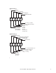
Diagram 1: Steam production: yellow LED - transient production "short flashing" steam < 1% time 1-19% time 20-29% time 90-99% time Diagram 2: Steam production: yellow LED - constant production "long flashing" steam < 1% time 1-19% time 20-29% time 90-99% time 100% time The yellow LED stays off when no steam is produced. Whereas it stays on continuously at 100% of the nominal production.
9.1.6 Maintenance Electrical Hazard: 1. Switch the cooling off unit at the Controller. 2. Turn the main disconnect switch to the OFF position. 3. Check for voltage. 4. Begin work if no voltage is present. The following work and checks can be carried out: - Check steam hoses, condensate hoses, water hoses and other parts of the humidifier for external effects or wear. - Flush out the water drain.
9.1.7 Malfunction causes and remedies Alarm: Humidifier defect The humidifier alarm is received by the controller and can be requested according to the equipment. InRoom advanced terminal: indication on the display In the event of this signal on the controller, look for the exact cause of the fault on the humidifier's printed circuit board in the electrical section of the cooling unit. If an alarm has been raised, the red light-emitting diode displays a flashing alarm code.
Alarm list Table 1 - Alarm types Type Description Reset (if alarm cause has been removed) Blocking CP-card stops humidifier. manual: to restart, turn the cpcard off and then on again. Disabling CP-card stops humidifier. • automatic • manual: to restart, turn the cp-card off and then on again. Note: the distinction between the automatic and manual reset is shown in the table below. Warning CP-card does not stop humidifier. Red LED Alarm codes: each code is displayed in sequence.
Table 2 - Alarms (continued) Red LED Description & Causes flashes 2x long Cylinder depleted Alarmrelay warning manual not Do maintenance or replace the cylinder. active 1. Check that the fill pipe from the mains to the humidifier and disabling manual active the internal pipe are not blocked or bent and that there is sufficient supply pressure (1-8 bar). 2. Check that the fill valve is properly working. 3.
9.2 Reheat The reheat is optional for your cooling unit. It is installed complete and integrated in the function and method of operation of the cooling unit. It is used to heat up the air. The following versions of the heater are available: - Electrical reheat Description Electrical reheat The reheat is connected in accordance with the electric diagram. It is controlled and monitored by the controller.
9.3 Raised floor stand 9.3.1 Floor stand for 60 Hz units The floor stand is used to adjust the height of the cooling unit to the height of the existing raised floor and consists of an encircling rectangular profile of galvanized steel with adjustable screw sockets. Anti-vibration pads are recommended between the concrete floor and base plate.
Floor stand parts: 1 - Welded frame 2 - Label front 3 - Floor stand foot 4 - Anti-vibration pad Each floor stand exists in eight heights. For heights from 102 to 254 mm (4 to 10 inch) the construction on top of the page is delivered, for heights from 305 to 610 mm (12 to 24 inch) the construction below is delivered. The available heights and their adjustment tolerances are shown in the table on page 68. The height within the drawings is indicated by dimension A.
For cabinet size 1 - 2 W1 17.5 mm 0.69 in 17.5 mm 0.69 in Cabinet Baugröße size Foot pad detail: 102 mm 829 mm 76 mm 102 mm For heights A from 102 to 254 mm (4 to 10 inch) mm (inch) 950 (37.38) 1359 (53.50) W1 mm (inch) 914 (36.00) 1324 (52.13) W2 mm (inch) 1016 (40.00) 1426 (56.13) W* mm (inch) 960 (37.75) =W W2* mm (inch) 1026 (40.
For cabinet size 3 - 4 W1 W3 17.5 mm 0.69 in 829 mm 17.5 mm 0.69 in Cabinet Baugröße size 3 4 W mm (inch) 1711 (67.38) 2108 (83.00) W1 mm (inch) 1676 (66.00) 2073 (81.63) W2 mm (inch) 1778 (70.00) 2175 (85.63) W3 mm (inch) 837 (32.94) 1035 (40.75) See foot pad detail on page 77.
For cabinet size 5 1949 mm 64.92 in 825 mm 32.46 in 17.5 mm 0.69 in 829 mm 17.5 mm 0.69 in 2476 mm 97.50 in For heights A from 102 to 254 mm (4 to 10 inch) 2512 mm 98.88 in 2578 mm 101.50 in For heights A from 305 to 610 mm (12 to 24 inch) 2512 mm 98.88 in 2578 mm 101.50 in See side view on page 68. 70 InRoom CW/DX – Operating Instructions See foot pad detail on page 77.
9.4 Air side connection 9.4.1 Discharge plenum The discharge plenum is available in two different versions for all upflow units. The discharge plenum will be set on top of the unit and be screwed with the unit. 400 (15.75) 500 (19.69) 400 (15.75) Discharge plenum with front and side grills L1 D B L1 C 600 2) (23.6 884 0) (34.8 Only one front grill for size 1, 2. Dimensions in mm (inch). Cabinet Baugröße size 1 2 3 4 5 B mm (inch) 1000 (39.37) 1400 (55.11) 1750 (68.90) 2150 (84.
9.5 Waterside connection 9.5.1 3-way-cooling water control valve The 3-way cooling water control valve is controlled by the InRoom relating to the condenser pressure by means of a pressure sensor at the refrigerant side. This valve controls the distribution of the water flow through the condenser and the bypass. Modell Type Ventilgröße Valve size 211/452 3/4 inch 311/612/862 1 inch f(PC1) condenser PC1 9.5.
9.6 Condensers 9.6.1 Voltage 208V / 3ph / 60Hz - 460V / 3ph / 60Hz Single circuit condensers Type Airflow cfm (m³/h) Number of fans SCS 120 SSA SCS 192 SSA SCS 312 SSA 8394 (14230) 19613 (33240) 17604 (29840) 2 2 2 Fan power consumption at 208-230V / 1 / 60Hz hp (kW) 2 x 1.23 (2 x 0.92) N/A N/A Fan power consumption at 208-230V / 3 / 60Hz hp (kW) 1 x 1.23 (1 x 0.92) 1 x 1.64 (1 x 1.22) 1 x 3.58 (1 x 2.67) 1 x 3.85 (1 x 2.87) 1 x 3.58 (1 x 2.67) 1 x 3.85 (1 x 2.
Condenser assignation to cooling units Type Application 1 Application 2 P A 211 SCS 120 SSA SCS 192 SSA P A 311 SCS 192 SSA SCS 312 DSA P A 452 SCS 252 DSA SCS 525 DSA P A 612 SCS 312 DSA SCS 683 DSA P A 862 SCS 525 DSA 2x SCS 525 DSA Application 1: Ambient temperature: 35°C (95°F), condensation temper ature: 49°C (120°F) Application 2: Ambient temperature: 46°C (115°F), condensation temperature: 55°C (131°F) SCS 120 SSA 32.75 in (832 mm) Electric box 29.
SCS 192 SSA - SCS 312 SSA SCS 252 DSA - SCS 312 DSA 48.25 in (1225 mm) Electric box 38.00 in (965 mm) Service switch Outlet Inlet 20.00 in (508 mm) 94.50 in (2400 mm) 99.50 in (2527 mm) SCS 525 DSA - SCS 683 DSA 48.25 in (1225 mm) 38.00 in (965 mm) Electric box Service switch Outlet 148.00 in (3759 mm) Inlet 20.00 in (508 mm) 51.
10. Maintenance 10.1 Safety instructions All maintenance work is to be carried out under strict compliance with the country-specific accident prevention regulations, especially the accident prevention regulations for electrical installations, refrigerating machines and equipment. Non-compliance with the safety instructions can endanger people and the environment. Maintenance work is only to be carried out on the units by authorized and qualified specialist staff.
10.3 Refrigerant circuit Refrigerant charge - Quantity and Purity Quantity - Check the sight glass and the LP switch. An insufficient charge causes the formation of bubbles in the sight glass or, in extreme cases, triggers the LP-switch. An operation with an insufficient refrigerant quantity over a longer period leads to a reduction of cooling capacity and to high superheating temperatures, which have a disadvantageous effect on the compressor lifetime.
Compressor The compressor is hermetically sealed with a lifetime supply of ester oil. The compressor crankcase is pressure lubricated by an internal pump with permanently lubricated, sealed bearings. Under normal operating conditions the ester oil should not need to be replaced. Ester oil is hygroscopic and absorbs moisture quickly when exposed to air. This could occur after repeated recharging of the refrigerant.
10.5 Water circuit Check the water circuit visually for leaks. A level indicator on the storage tank, if applicable, provides a visual indication of changes in the water level. Lower water levels allow air in the circuit which reduces the heat transfer capacity of the chilled water circuit and is detrimental to the operation of the pump. Condenser (only on G, GE, GCW units) Check for water side contamination of the plate condenser by comparing the cooling water inlet temperature to the outlet temperature.
APC Worldwide Customer Support Customer support for this or any other APC product is available at no charge in any of the following ways: • Visit the APC Web site to access documents in the APC Knowledge Base and to submit customer support requests. – www.apc.com (Corporate Headquarters) Connect to localized APC Web sites for specific countries, each of which provides customer support information. – www.apc.com/support/ Global support searching APC Knowledge Base and using e-support.