Installation InRow™ RC ACRC100 ACRC103
This manual is available in English on the enclosed CD. Dieses Handbuch ist in Deutsch auf der beiliegenden CD-ROM verfügbar. Deze handleiding staat in het Nederlands op de bijgevoegde cd. Este manual está disponible en español en el CD-ROM adjunto. Ce manuel est disponible en français sur le CD-ROM ci-inclus. Questo manuale è disponibile in italiano nel CD-ROM allegato. 本マニュアルの日本語版は同梱の CD-ROM からご覧になれます。 Instrukcja Obsługi w jezyku polskim jest dostepna na CD.
American Power Conversion Legal Disclaimer The information presented in this manual is not warranted by the American Power Conversion Corporation to be authoritative, error free, or complete. This publication is not meant to be a substitute for a detailed operational and site specific development plan.
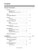
Contents General Information ........................................................ 1 Overview . . . . . . . . . . . . . . . . . . . . . . . . . . . . . . . . . . . . . . . . . . . . . . . . 1 Save these instructions . . . . . . . . . . . . . . . . . . . . . . . . . . . . . . . . . . . 1 Manual updates . . . . . . . . . . . . . . . . . . . . . . . . . . . . . . . . . . . . . . . . . . 1 Cross-reference symbol used in this manual . . . . . . . . . . . . . . . . . 1 Safety . . . . . . . . . . . . . . . . .
Mechanical Connections . . . . . . . . . . . . . . . . . . . . . . . . . . . . . . . . . . 16 Piping . . . . . . . . . . . . . . . . . . . . . . . . . . . . . . . . . . . . . . . . . . . . . . . . . 16 Connect piping . . . . . . . . . . . . . . . . . . . . . . . . . . . . . . . . . . . . . . . . . 17 Chiller . . . . . . . . . . . . . . . . . . . . . . . . . . . . . . . . . . . . . . . . . . . . . . . . . 19 CDU . . . . . . . . . . . . . . . . . . . . . . . . . . . . . . . . . . . . . . . . . . . . . . . . .
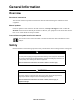
General Information Overview Save these instructions This manual contains important instructions that must be followed during the installation of this equipment. Manual updates Check for updates to this manual on the APC Web site, www.apc.com/support. Click on the User Manuals link and enter the manual part number or SKU for your equipment in the search field. See the back cover of this manual for the part number.
WARNING DAMAGE TO EQUIPMENT OR PERSONNEL The equipment is heavy and can easily be tipped. For safety purposes, adequate personnel must be present when moving this equipment. Failure to follow these instructions can result in death, injury, or equipment damage. CAUTION HAZARD TO EQUIPMENT OR PERSONNEL All work must be performed by American Power Conversion (APC™) by Schneider Electric authorized personnel. Failure to follow these instructions can result in injury or equipment damage.
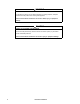
Inspecting the Equipment Inspect for missing components. All shipped loose components are identified by part number and description on the bill of lading. Ensure each item is present before accepting delivery of the unit. Filing a claim. If damage has occurred, or if shipped loose parts are missing, report it immediately to the delivering carrier and note the problem on the receiving copy of the bill of lading. Failure to do so will result in replacement parts and repairs being billed to the customer.
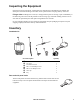
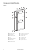
Component Identification na1542a Exterior 4 1 Removable rear door 8 Door lock (front and rear doors) 2 Side panel latch 9 Top network wiring access 3 Removable side panel : Top supply (inlet) 4 Caster ; Top condensate drain 5 Adjustable leveling foot < Top return (outlet) 6 Display interface = Top power cord access 7 Removable front door InRow RC Installation
na1556a Interior 1 Air filter ; Bottom supply connection (optional) 2 Top supply connection (optional) < Drain valve (cap is installed at factory) 3 Top return connection (optional) = User interface connection box 4 2-way supply valve (1-inch) > Power supply unit (PSU) 5 Flow meter ? Bottom condensate drain pan 6 3-way valve @ Condensate floats 7 2-way or 3-way valve with flow control actuator A Coil 8 2-way valve (3/4-inch) bypass shut-off B Top condensate drain pan 9 Bot
na2236a User interface connection panel 6 1 A-Link ports 5 Control RS-485 port 2 Reset button 6 Form C alarm contacts and shutdown input 3 Ethernet port 7 Configuration port 4 Building management system (BMS) RS-485 port 8 Leak detector port InRow RC Installation
Room Preparation During the design of the data center, consider ease of entry for the equipment, floor loading factors, and accessibility to piping and wiring. Seal the room with a vapor barrier to minimize moisture infiltration. (Polyethylene film is recommended for ceiling and wall applications.) Apply rubber- or plastic-based paints to concrete walls and floors. Insulate the room to minimize the influence of exterior heat loads.
Piping Diagrams With cooling distribution unit (CDU) To customersupplied chiller Top piping InRow RC CDU Supports up to 12 units Bottom piping CDU InRow RC Supports up to 12 units na2608a To customersupplied chiller Flex hose or copper tubing Y-strainer with 20 mesh screen (field installed) Copper tubing Shutoff valve (field-installed) Note: Install isolation valves and particulate strainers with 20 mesh stainless steel screen (opening size = 865 micron) in the supply line between the chiller
Without CDU Top piping To customersupplied chiller InRow RC InRow RC Bottom piping InRow RC InRow RC na2609a To customersupplied chiller Flex hose or copper Y-strainer with 20 mesh screen (field installed) Shutoff valve (field-installed) Copper tubing Circuit setter Note: Install isolation valves and particulate strainers with 20 mesh stainless steel screen (opening size = 865 micron) in the supply line between the chiller and the CDU.
Internal piping diagram In Out From Coils Out Full Bypass Out na1736b In Full Open 10 1 Entering water union (top piping) 8 Entering water union (bottom piping) 2 Leaving water union (top piping) 9 Bottom condensate pan 3 3-way actuator control valve—3/4 in : Bottom coil 4 Bypass shutoff ball valve—3/4 in ; Top condensate pan 5 Condensate drain < Top coil 6 Leaving water union (bottom piping) = Flow meter 7 Condensate pump > Inlet shutoff valve—1 in InRow RC Installatio
117 (4.6) 80 (3.15) 152.00 (5.98) 67.80 (2.67) 48.00 (1.89) 0 222 (8.74) 149 (5.87 ) 73 (2.87) 50 (1.97) 0 Piping and electrical access locations 0 114 (4.59) 152 (5.98) 190.55 (7.50) 229 (9.02) 507.50 (19.98) Bottom na1557a Top Supply 132 (5.19) 373 (14.68) Return Interior pipe dimensions Supply 588 (23.14) 403 (15.86) Return Dimensions are shown in mm (in).
na1551a Weights and Dimensions Dimensions are shown in mm (in). Net weight (equipment only) 12 162.77 kg (358.
Installation Removing Doors and Panels WARNING MOVING PARTS HAZARD • Do not open doors and panels if the equipment is operating Failure to follow these instructions can result in death, serious injury, or equipment damage. CAUTION UNPROTECTED PARTS Be careful when placing doors when removed from the equipment. Spring latches are easily damaged. Failure to follow these instructions can result in equipment damage.
Positioning the Equipment Service access na1565a An area of 1143 mm (45 in) of clear floor space in front and 914.4 mm (36 in) in back of the equipment is required for service. All required maintenance can be performed from the front or back of the equipment. Dimensions are shown in mm (in). Leveling The leveling feet provide a stable base if the floor is uneven, but cannot compensate for a badly sloped surface.
Stabilizing the Equipment Floor brackets To prevent the equipment from moving from its final location (if it is not joined with an enclosure), use the included bolt-down kit (AR7701). Follow the installation instructions included with the kit. Joining to enclosures NetShelter™ SX enclosure. Two joining brackets are installed on the front and rear of the equipment. Depending on how the holes on the joining brackets are used, you have the option of either 24-in or 600-mm spacing. 2.
Mechanical Connections Piping Note: Ensure coolant water quality complies with guidelines set forth in IB0125GB001. Water. Install shutoff Hot Aisle Containment valves for routine service and emergency isolation of the equipment. When a CDU is not used, you must install circuit setters to regulate the chilled water flow for each InRow RC air NetShelter conditioner. See “Piping Diagrams,” beginning on page 8. CDU NetShelter NetShelter Top piping examples shown PDU UPS Layout and piping considerations.
Connect piping See “Piping Diagrams,” beginning on page 8, for recommended valve, flexible adapter, and strainer installation locations. 1. Route all piping 1 to the InRow RC in compliance with all local and national codes. Note: Circuit setters are required to regulate the flow of chilled water to each piece of equipment. When a CDU is used in conjunction with the equipment, circuit setters are not required, as the CDU provides the flow-regulating function.
na1575a Condensate pump. The pump is factory-wired and piped internally to the lower condensate pan. The pump is capable of moving liquid a maximum of 15.2 m (50 ft), including a maximum lift of 4.9 m (16 ft). For example, if your lift is 3 m (10 ft), you have 12.2 m (40 ft) of usable run. The pump also uses an on-board condensate high level float switch, which is wired into the InRow RC alarm input for local and remote alarm capabilities.
Condensate pump drain installation. The condensate drain line is coiled inside the equipment, allowing you to route the condensate drain line for either top or bottom use. See the table “Piping and electrical access locations” on page 11 for more information. Use the provided grommets to properly secure and protect the condensate drain line. Top routing Note: Comply with all local codes when installing the condensate drain line to the proper drain system.
Filling and Purging When the equipment is properly piped, begin the filling process (top piping configuration shown). DANGER HAZARD OF ELECTRIC SHOCK, EXPLOSION, OR ARC FLASH Turn off all power supplying this equipment before working on the equipment. Failure to follow these instructions will result in death or serious injury. 1. Open the 2-way supply valve and the 2-way bypass shutoff valve. 2. Using a 2.5-mm hex key, turn the flow control actuator to the fully open position.
3. Slightly open the top coil vent. 4. At the water supply, open the appropriate valves to begin letting water slowly enter the equipment. 5. At the equipment, close the top coil vent when water begins slowly flowing out of the vent. Top coil vent a. Open all valves (no greater than 76 l/m [20 gpm]), allowing the water supply to reach the highest possible flow to the equipment for 45 seconds. na1768a 6. At the water supply: b. Close the valves to a 3.8–11.4 l/m (1–3 GPM) flow for 60 seconds. c.
Electrical Connections The following electrical connections are required in the field: • Feeds A and B • A-Link • Network Management Card • Temperature sensor • Communication (building management system) See the electrical schematic (located on the lid of the electrical box) for all electrical connections. Make all electrical connections in accordance with national and local codes. See the InRow RC nameplate for voltage and current requirements.
Power connections Power cords may be routed through the top of the equipment (standard) or through the bottom (optional). Top wiring configuration Screws Top power cord entrance (standard). 1. Route power cords through the equipment to the top power cord access, as shown. 2. Push the power cords through the hole at the top power cord entrance. 3. Secure the plate to the underside of the equipment top with four Phillips screws (provided). Plate na1581a 4.
User interface connection pinout Shutdown input contacts and alarm output contacts CONTROL na1579a MODBUS 1 A-Link port Pin 1=High; Pin 2=Low; Pins 3, 6=Perf Power; Pins 4, 5=Ground 9 24 Vdc (bias) 2 Reset button : 12 Vdc (bias) 3 Network port ; Return (bias) Pins 1-8 = Standard RJ-45 24 4 Shield/ground < NO (normally open contact) 5 A-=True = COM (common contact) 6 B+=True > NC (normally closed contact) 7 Shutdown - ? RS-232 console port (see the InRow RC Service Manual)
A-Link ports Note: All input and output connections should be wired as Class 2 circuits. Depending on the equipment configuration, additional control connections may be required for the A-Link remote communications through APC Network Management Card support or other equipmentmonitoring software. A special RJ-45 terminator is provided and must be installed if both A-Link ports are not otherwise used, as shown. Active flow controllers (AFC).
Network port Second InRow RC Switch/Hub 1 26 LAN cable (10/100 Base-T) InRow RC Installation Last InRow RC na2247a First InRow RC
Modbus First InRow RC Second InRow RC Last InRow RC na2248a Modbus MASTER 1 150Ω termination resistor (provided) 2 Modbus cable (RS-485) na2249a Control connector 1 150Ω termination resistor (provided) 2 Control cable (RS-485) 3 InRow RC Installation Peripheral device (example: chiller) 27
Form C alarm contacts and shutdown input Remote switch using internal power (24 Vdc shown) Field-supplied voltage (12/24 Vdc or Vac) A relay internal to the user interface is typically controlled by a user-defined alarm (malfunctioning fans, for example). Before an alarm is detected, the voltage on the COM terminal is routed to the NC terminal. When the alarm is activated, the relay is energized, causing the voltage on the COM terminal to be routed to the NO terminal.
Temperature sensor Remote temperature sensor na2271a Note: The remote temperature sensor comes coiled inside the equipment as shown, and must be mounted as follows, or the equipment will not operate properly. gen0744a The remote temperature sensor monitors the room temperature, monitoring the environment surrounding the cooling equipment to ensure that the conditioned air is cooling the area. Install the temperature sensor. 1.
APC Worldwide Customer Support Customer support for this or any other APC product is available at no charge in any of the following ways: • Visit the APC Web site to access documents in the APC Knowledge Base and to submit customer support requests. – www.apc.com (Corporate Headquarters) Connect to localized APC Web sites for specific countries, each of which provides customer support information. – www.apc.com/support/ Global support searching APC Knowledge Base and using e-support.