Operation InRow® SC ACSC100 ACSC101
This manual is available in English on the enclosed CD. Dieses Handbuch ist in Deutsch auf der beiliegenden CD-ROM verfügbar. Deze handleiding staat in het Nederlands op de bijgevoegde cd. Este manual está disponible en español en el CD-ROM adjunto. Ce manuel est disponible en français sur le CD-ROM ci-inclus. Questo manuale è disponibile in italiano nel CD-ROM allegato. 本マニュアルの日本語版は同梱の CD-ROM からご覧になれます。 Instrukcja Obsługi w jezyku polskim jest dostepna na CD.
Contents General Information ........................................................ 1 Overview . . . . . . . . . . . . . . . . . . . . . . . . . . . . . . . . . . . . . . . . . . . . . . . . 1 Safety . . . . . . . . . . . . . . . . . . . . . . . . . . . . . . . . . . . . . . . . . . . . . . . . . . . 2 Commissioning ............................................................... 3 Inspection Checklists . . . . . . . . . . . . . . . . . . . . . . . . . . . . . . . . . . . . . .
Control the Environment . . . . . . . . . . . . . . . . . . . . . . . . . . . . . . . . . . 15 Setpoints . . . . . . . . . . . . . . . . . . . . . . . . . . . . . . . . . . . . . . . . . .15 Run hours . . . . . . . . . . . . . . . . . . . . . . . . . . . . . . . . . . . . . . . . .16 Thresholds . . . . . . . . . . . . . . . . . . . . . . . . . . . . . . . . . . . . . . . . .16 Service intervals . . . . . . . . . . . . . . . . . . . . . . . . . . . . . . . . . . . .17 Display Settings . . . . . . . . . . .
Access a Configured Network Management Card . . . . . . . . . . . . . .32 Overview . . . . . . . . . . . . . . . . . . . . . . . . . . . . . . . . . . . . . . . . . . 32 Web interface . . . . . . . . . . . . . . . . . . . . . . . . . . . . . . . . . . . . . . 32 Telnet and SSH . . . . . . . . . . . . . . . . . . . . . . . . . . . . . . . . . . . . . 33 Simple Network Management Protocol (SNMP) . . . . . . . . . . . . . 34 FTP/SCP . . . . . . . . . . . . . . . . . . . . . . . . . . . . . . . . . . . . . . .
American Power Conversion Legal Disclaimer The information presented in this manual is not warranted by the American Power Conversion Corporation to be authoritative, error free, or complete. This publication is not meant to be a substitute for a detailed operational and site specific development plan.
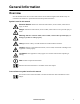
General Information Overview Note the definitions for the icons here and be observant for them throughout this manual. They are intended to call attention to potential hazards and important information. Symbols used in this manual Electrical Hazard: Indicates an electrical hazard which, if not avoided, could result in injury or death. Danger: Indicates a hazard which, if not avoided, could result in severe personal injury or death.
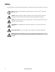
Safety Read and adhere to the following important safety considerations when working with this cooling unit. Note: All work must be performed by American Power Conversion (APC®) authorized personnel only. Caution: Keep your hands, clothing, and jewelry away from moving parts. Check the equipment for foreign objects before closing the doors and starting the equipment. Heavy: The equipment is heavy. For safety purposes, at least two people must be present when moving this equipment.
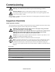
Commissioning Warning: APC authorized personnel must perform the following procedures. Electrical Hazard: Perform Lockout/Tagout procedures on the cooling unit before servicing the cooling unit. Failure to remove power before servicing this equipment could result in serious injury or death. After installation is complete, verify that all components are working properly and that the cooling unit is ready to begin operation.
Electrical inspection checklist The electrical inspection verifies that all electrical connections are secure and correct and that the cooling unit is properly grounded. Electrical Hazard: All electrical wiring must comply with local and national codes and regulations. Electrical Hazard: The equipment must be grounded (do not use a water-pipe ground). Ensure that the: Incoming voltages match the phase and voltage listed on the nameplate.
User interface inspection checklist The user interface inspection verifies that the sensors and internal communications links of the cooling unit are installed properly. Ensure that: An A-Link bus is connected to each cooling unit in the group and a terminator is plugged into all unused A-Link connectors. The input contacts and output relays are connected correctly. The building management system (if used) is connected correctly.
Operation Display Interface Item 6 Function Critical Alarm LED (red) When illuminated, a critical alarm condition exists that requires your immediate attention. Warning Alarm LED (yellow) When illuminated, a warning alarm condition exists. Failure to correct this condition could cause a critical alarm. Check Log LED (yellow) When illuminated, at least one new event has been logged since the last time the log was checked.
Using the Display Interface Every time you apply power to the cooling unit, the display interface initializes, causing the LEDs to cycle and the alarm tone to activate. Scrolling status screens After start-up, the interface displays the firmware revision number of the display interface. The display interface then scrolls automatically and continuously through screens of status information.
Navigating the main menu Selector arrows. Press the up or down arrow key to move the selector arrow to a menu option or setting. Press the ENTER key to view the selected screen or modify the setting. Continue arrows. Continue arrows indicate that additional options or settings are available on a menu or status screen. Press the up or down arrow key to view the additional items.
Using the Path statement Select the main- and sub-menu options specified in the path statement to view or configure a setting. The path statement lists the main- and sub-menu items you select to navigate to the item to view or modify. The parts of the path statement are defined below: Path: Main > Set Password >Change Passwords Main > Your starting point is the main menu. Set Password > Scroll to and select this option from the main menu.
Start the cooling unit Path: Main Menu > On/Standby To start the cooling unit, change the setting to On by pressing the key to toggle from Standby to On. At that point, the fans will start or Unit startup in progress will appear if the Start-Up Delay option is set to restart multiple cooling units sequentially.
General Configuration The cooling group configuration options are set during the commissioning of the cooling units in the cooling group. Caution: This procedure must be performed by APC authorized personnel only. Changing the settings incorrectly can cause malfunctions to your cooling unit. Cooling unit configuration Path: Main > Configure Unit > General Use the General menu to set the following: Start-up Delay. The delay begins when the cooling unit is started and initialized.
Contacts View the state of input and output contacts Path: Main > Configure Unit > Discrete I/O Each cooling unit supports a user-defined input contact and a user-defined output contact. Each contact monitors a sensor and responds to changes in the state of the sensor (open or closed). Input State. Indicates the actual state of the input contact (Open or Closed). A cooling unit is On when the state is normal and in Standby when the state is not normal. Output State.
Cooling Group Configuration Use the cooling group configuration settings to add cooling units to the group and to define group operation. Caution: APC recommends that this procedure be performed by APC authorized personnel only. The settings in the Configure Group menu are defined by APC authorized personnel when the cooling group is commissioned.
Identify the cooling unit Path: Main >Set Identification The Set Identification menu contains settings that identify the name and location of the cooling unit. Name. Assign a Name of up to 40 alpha-numeric characters to this cooling unit. Location. Enter the Location, up to 40 alpha-numeric characters, of the cooling unit. Note: Only the first 19 characters (of the 40 that are possible to enter) will display on the display interface.
Control the Environment The main function of the cooling unit is to remove waste heat and return treated air to the room at the required temperature. The control strategies employed by the cooling unit depend upon the deployment strategy of the cooling group. In an In-row environment, the cooling unit supplies constant-temperature supply air to the common cold aisle. The fan speed is modulated to ensure that the required volume of air reaches the IT equipment.
Run hours Path: Main > View Run Hours The cooling unit records the number of hours each of its components has operated. When a component is replaced, use the Reset option to reset the run hours for the displayed component to zero.
Service intervals Path: Main > Service Intervals The air filters should be serviced regularly. The service interval depends on environmental cleanliness. • Air Filter Interval: Set the number of weeks before service is required for the Air Filter Interval. The default is 18 weeks. • Alarm: The interval setting has an alarm (Enable or Disable). If enabled, an audible alarm activates when the interval has elapsed. The alarm is cleared by selecting Clear Alarms in the main menu.
Display Settings Set display settings, including the time and date, units, passwords, and time-out settings. You can also adjust contrast, key click, beeper volume, and beep on alarm. Password & time-out Path: Main > Set Password Note: The default user password is apc (lowercase). Change passwords. Set the Admin and Device passwords. 1. Move the selector arrow next to the Change Passwords option and press the ENTER key. 2. Select the password to change (either Admin or Device). 3.
Configure display Path: Main > Configure Display Contrast. Adjust the visibility of the screen text. Lower numbered settings provide darker text; higher numbers provide lighter text. Settings range from 0–7. Key Click. Set to ON or OFF will enable or disable an audible tone that sounds every time a key is pressed on the display interface. Beeper Volume. Set the volume (Low, Medium, High or OFF) of the audible tone that sounds every time a key is pressed on the display interface. Beep on Alarm.
Network Configuration The cooling unit is shipped with a Network Management Card that enables the cooling unit to be managed over a network. Configure the network settings for the Network Management Card for this cooling unit from the display interface. The management card allows remote control and configuration of the equipment. Configure network Path: Main > Configure Network MAC Address. Displays the unique network identifier assigned to each equipment at the factory. Boot Mode.
View Status Readings The display interface has several options for viewing the status of the cooling unit, the cooling group to which the cooling unit belongs, and the environment being controlled. The status readings for the cooling unit are available under the View Unit Status option in the main menu, and status readings for the cooling group are available under the View Group Status option on the main menu or on the scrolling status screens.
Cooling group status Path: Main > View Group Status View information about the cooling group. Cool Output. The combined output of the cooling group. Cool Demand. The cooling output required to meet the current heat load of the conditioned space. Cool Setpt. The temperature you set to maintain the room environment. Air Flow. The combined airflow output of the cooling units in the cooling group. Max Rack. The highest rack temperature reported by any cooling unit in the cooling group. Min Rack.
Event Log The event log saves status information and a message each time a change in the cooling unit is detected. Alarms events are recorded in the log and displayed on the active alarm screens. Status (informational) events and system configuration changes are only displayed in the event log. The number of messages in the event log is limited to 500. When the number of messages in the event log reaches 500, the oldest message will be dropped from the list every time a new message is added to the log.
Alarm messages and suggested actions Displayed Alarm Message Severity Action Required Air Filter Clogged Warning • Clean or replace the air filter. • If the problem persists, refer to the back page of this manual for contact information. Air Filter Run Hours Violation Warning • Reset the Air Filter Run Hours after the air filter is cleaned or replaced. A-Link Isolation Relay Fault Critical • A hardware failure exists. For assistance, refer to the back page of this manual for contact information.
Displayed Alarm Message Severity Action Required Filter Sensor Fault Warning • A hardware failure exists. For assistance, refer to the back page of this manual for contact information. High Discharge Pressure Alarm Critical • For assistance, refer to the back page of this manual for contact information. Internal Communication Fault Critical • A hardware failure exists. For assistance, refer to the back page of this manual for contact information.
Displayed Alarm Message Severity Action Required Input Contact Fault Warning • Make sure the Input Normal state is defined correctly in the Configure Unit> Discrete I/O screen. See page 17 for more information. • Clear the problem that caused the input contact switch to change from the normal state. • If the problem persists, refer to the back page of this manual for contact information.
Network Management Card Quick Configuration The cooling unit is shipped with a Network Management Card that enables the cooling unit to be managed over a network. Configure the Network Management Card to control this cooling unit through a network. Overview You must configure the following TCP/IP settings before the Network Management Card can operate on a network: • IP address of the Network Management Card • Subnet mask • Default gateway Caution: Never use the loopback address (127.0.0.
APC Device IP Configuration Wizard You can use the APC Device IP Configuration Wizard at a computer running Microsoft® Windows 2000, Windows Server 2003, or Windows XP to configure a Network Management Card. Note: Most software firewalls must be temporarily disabled for the Wizard to discover unconfigured Network Management Cards. To configure one or more Network Management Cards from a user configuration file, see the User’s Guide on the CD. 1. Insert the CD into a computer on your network. 2.
BOOTP. For the Network Management Card to use a BOOTP server to configure its TCP/IP settings, it must find a properly configured RFC951-compliant BOOTP server. 1. In the BOOTPTAB file of the BOOTP server, enter the MAC address of the Network Management Card, the IP address, the subnet mask, default gateway, and an optional bootup file name. Look for the MAC address on the display interface (Path: Main > Configure Network) or on the label on the back of the Network Management Card. 2.
Local access to the control console You can use a computer connected to the serial port on the main board holding the Network Management Card to access the control console. 1. Select a serial port at the local computer, and disable any service that uses that port. 2. Use the provided configuration cable to connect the selected port to the serial port on the main board holding the Network Management Card. 3.
Control console After you log on at the control console, as described in “Local access to the control console” on page 30 or “Remote access to the control console” on page 30: 1. Choose Network from the Control Console menu. 2. Choose TCP/IP from the Network menu. 3. If you are not using a BOOTP or DHCP server to configure the TCP/IP settings, select the Boot Mode menu and then select Manual boot mode. 4. Set the System IP, Subnet Mask, and Default Gateway address values.
Access a Configured Network Management Card Overview After the Network Management Card is running on your network, you can access the configured Network Management Card through the following interfaces: • Web interface (HTTP or HTTPS protocol) • Telnet or Secure SHell (SSH) • SNMP • FTP or Secure CoPy (SCP) to upgrade firmware • Modbus For more information on the interfaces, see the User’s Guide. Web interface Use Microsoft Internet Explorer® (IE) 5.
Telnet and SSH You can access the control console through Telnet or Secure SHell (SSH), depending on which is enabled. Select the Administration tab, the Network option on the top menu bar, and then the Access option under Console on the left navigation menu. By default, Telnet is enabled. Enabling SSH automatically disables Telnet. Telnet for basic access. Telnet provides the basic security of authentication by user name and password, but not the high-security benefits of encryption.
Simple Network Management Protocol (SNMP) SNMPv1 only. After you add the PowerNet® MIB to a standard SNMP MIB browser, you can use that browser to access the Network Management Card. All user names, passwords, and community names for SNMP are transferred over the network as plain text. The default read community name is public; the default read/write community name is private. SNMPv3 only. For SNMP GETs, SETs, and trap receivers, SNMPv3 uses a system of user profiles to identify users.
Recover From a Lost Password You can use a local computer (a computer that connects to the Network Management Card through the serial port) to access the control console. 1. Select a serial port at the local computer, and disable any service that uses that port. 2. Connect the provided RS-232 configuration cable to the selected port on the computer and to the RS-232 console port at the Network Management Card. 3.
Maintenance Monthly Preventive Maintenance The following pages can be photocopied and used during the maintenance procedures. After they have been filled out, save them for future reference.
Mechanical Electrical Hazard: Turn off the cooling unit and disconnect all power sources. Perform Lockout/ Tagout procedures before performing any electrical or mechanical service. Wear appropriate personal protective equipment when checking hazardous voltages. Check the fans. All components should be moving freely, with no signs of binding or damage. Verify that the condensate line is flowing freely. Electrical Electrical Hazard: Turn off the cooling unit and disconnect all power sources.
Quarterly Preventive Maintenance * Perform all the Monthly Preventive Maintenance items and the items below. Prepared By: _________________________________ Model Number: ______________________________ Serial Number: _______________________________ Date: _________________ Mechanical Electrical Hazard: Turn off the cooling unit and disconnect all power sources. Perform Lockout/ Tagout procedures before performing any electrical or mechanical service.
Semi-Annual Preventive Maintenance * Perform all the Monthly/Quarterly Preventive Maintenance items and the items below. Prepared By: _________________________________ Model Number: ______________________________ Serial Number: _______________________________ Date: _________________ Cleanliness Check the cleanliness of the evaporator and condenser coils. Clean if required.
Troubleshooting Problem Possible Cause Corrective Action Fans fail to start • Cooling Unit shutdown due to an external command • Temporarily remove the user contact cable, if it is connected. • Single fan fails to start • Confirm that the fan is seated properly and fully engaged. • Replace the fan if it is faulty. • Improper placement of remote temperature sensor • Verify that the remote temperature sensor is properly located in the IT rack. • Dirty filter • Clean the filter.
Problem Possible Cause Corrective Action Local display is not operational, but cooling unit operates • Local display not connected properly • Verify that the local display cable is connected properly. Incorrect air pressure • False filter clogs • Verify that the ends of the clear plastic air tubes are not obstructed. • Verify that the clear plastic air tubes are connected to the controller. • Verify that the clear plastic air tubes are not pinched.
Warranty One-Year Factory Warranty The limited warranty provided by American Power Conversion (APC®) in this Statement of Limited Factory Warranty applies only to products you purchase for your commercial or industrial use in the ordinary course of your business. Terms of warranty American Power Conversion warrants its products to be free from defects in materials and workmanship for a period of one year from the date of purchase.
IN NO EVENT SHALL APC, ITS OFFICERS, DIRECTORS, AFFILIATES OR EMPLOYEES BE LIABLE FOR ANY FORM OF INDIRECT, SPECIAL, CONSEQUENTIAL OR PUNITIVE DAMAGES, ARISING OUT OF THE USE, SERVICE OR INSTALLATION, OF THE PRODUCTS, WHETHER SUCH DAMAGES ARISE IN CONTRACT OR TORT, IRRESPECTIVE OF FAULT, NEGLIGENCE OR STRICT LIABILITY OR WHETHER APC HAS BEEN ADVISED IN ADVANCE OF THE POSSIBILITY OF SUCH DAMAGES.
APC Worldwide Customer Support Customer support for this or any other APC product is available at no charge in any of the following ways: • Visit the APC Web site to access documents in the APC Knowledge Base and to submit customer support requests. – www.apc.com (Corporate Headquarters) Connect to localized APC Web sites for specific countries, each of which provides customer support information. – www.apc.com/support/ Global support searching APC Knowledge Base and using e-support.