User Manual English APC SmartSmart-UPS® RT 7500/10000 VA 200200-240 VAC 6U Tower/Rack Mount Uninterruptible Power Supply 990-1216B 02/2004
Introduction The APC Smart-UPS RT is a high-performance, uninterruptible power system (UPS), designed to prevent blackouts, brownouts, sags and surges from reaching your computers, servers, and other sensitive electronic equipment. 1: INSTALLATION Attention: Read the safety information sheet before installation. Unpacking Inspect the UPS upon receipt. Notify the carrier and dealer if there is damage. The packaging is recyclable; save it for reuse or dispose of it properly.
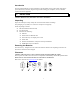
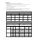
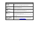
Hardwiring Attention: Wiring must be performed by a qualified electrician. 1. 2. 3. 4. 5. 6. Install a utility circuit breaker in accordance with local electrical codes (see tables below) for input wiring only. Switch the UPS input circuit breaker (see A) and utility circuit breakers OFF. Remove the access panel (see B). Remove circular knockouts. Run wires through access panel to terminal blocks. Wire to ground block first. Adhere to all national and local electrical codes. (See tables and graphics.
7. XLI model only: For three-phase input, set the Input Phase Selector switch (see C) to ‘3’. For single-phase input, leave switch in default position of ‘1’. XLT/XLJ/XLTW MODELS OUTPUT L1A L2A INPUT L1 L2 A B XLI MODEL OUTPUT L1A N1 INPUT L1 L2 A L3 N C B 8. Switch the circuit breakers ON. 9. Check line voltages. 10. Replace the access panel.
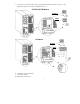
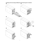
Installing and Connecting the Batteries and Attaching the Front Bezel 4
CONNECTING POWER AND EQUIPMENT TO THE UPS 1. Hardwire the UPS (see Hardwiring). 2. Connect equipment to the UPS (cables not included for XLT/XLJ/XLTW models). 3. Turn on all connected equipment. To use the UPS as a master on/off switch, be sure that all connected equipment is switched ON. 4. Press the button on the front panel to power up the UPS. The battery charges to 90% capacity during the first three hours of normal operation.
BASIC CONNECTORS Serial Port Ethernet Port EPO Terminal TVSS Screw External Battery Pack Connectors Power management software and interface kits can be used with the UPS. Use only interface kits supplied or approved by APC. Connect the UPS to the network. (Located on Web/SNMP card.) The optional Emergency Power Off (EPO) feature allows connected loads to be immediately de-energized from a remote location, without switching to battery operation (see EPO Option).
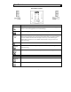
2: OPERATION FRONT DISPLAY PANEL Indicator Description Online The UPS is drawing utility power and performing double conversion to supply power to connected equipment (see Troubleshooting). On Battery The UPS is supplying battery power to the connected equipment. Bypass The UPS is in bypass mode, sending utility power directly to connected equipment.
Feature Function Normal /Bypass Manually switch connected equipment to bypass mode, so that utility power is sent directly to connected equipment. Battery operation is not available while the UPS is in bypass mode. (See Troubleshooting.) Cold Start This is not a normal condition. Supply immediate battery power to the UPS and connected equipment (see Troubleshooting). Press and hold the button to power up the UPS and connected equipment. The UPS will emit two beeps.
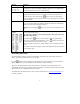
3: USER CONFIGURABLE ITEMS NOTE: SETTINGS ARE MADE THROUGH SUPPLIED POWERCHUTE SOFTWARE, WEB/SNMP CARD, OPTIONAL SMART SLOT ACCESSORY CARDS OR TERMINAL MODE. FUNCTION FACTORY DEFAULT USER SELECTABLE CHOICES DESCRIPTION Automatic Self-Test Every 14 days (336 hours) Every 7 days (168 hours), Every 14 days (336 hours), On Startup Only, No Self-Test Set the interval at which the UPS will execute a self-test. UPS ID UPS_IDEN Up to eight characters to define the UPS Uniquely identify the UPS, (i.e.
NOTE: SETTINGS ARE MADE THROUGH SUPPLIED POWERCHUTE SOFTWARE, WEB/SNMP CARD, OPTIONAL SMART SLOT ACCESSORY CARDS OR TERMINAL MODE. FACTORY DEFAULT FUNCTION USER SELECTABLE CHOICES DESCRIPTION High Bypass Point +10% of output voltage setting +5%, +10%, +15%, +20% Maximum voltage that the UPS will pass to connected equipment during internal bypass operation.
EPO (Emergency Power Off) Option The output power can be disabled in an emergency by closing a switch connected to the EPO. Adhere to national and local electrical codes when wiring. The switch should be connected in a normally open switch contact. External voltage is not required; the switch is driven by 12V internal supply. In closed condition, 2mA of current are drawn. The EPO switch is internally powered by the UPS for use with non-powered switch circuit breakers.
Terminal Mode to Configure UPS Parameters Terminal Mode is a menu driven interface that enables enhanced configuration of the UPS. Connect the serial cable to the serial port on the back of the UPS. When using PowerChute® Network Shutdown software: 1. 2. Open a terminal program. Example: HyperTerminal • From the Desktop, go to Start => Programs => Accessories => Communication =>HyperTerminal. Double-click on the HyperTerminal icon. Follow the prompts to choose a name and select an icon.
4: STORAGE, MAINTENANCE, AND TRANSPORTING Storage Store the UPS covered and positioned as for proper functioning, in a cool, dry location, with the batteries fully charged. (Batteries must be charged every six months.) Store at: 0-50,000 ft (0 - 15,000 m) 5°-113° F ( -15 - 45 ° C) Replacing the Battery Module(s) This UPS has easy to replace, hot-swappable battery modules. Replacement is a safe procedure, isolated from electrical hazards.
5: TROUBLESHOOTING Use the table below to solve minor installation and operation problems. Refer to the APC web site, www.apc.com, for assistance with complex UPS problems. PROBLEM AND POSSIBLE CAUSE SOLUTION UPS WILL NOT TURN ON Batteries are not connected properly. button not pushed. Check that the battery connectors are fully engaged. Press the button once to power the UPS and the connected equipment. UPS not connected to utility power supply.
PROBLEM AND POSSIBLE CAUSE SOLUTION BYPASS LED ILLUMINATES The bypass switch has been turned on manually or through an accessory. If bypass is the chosen mode of operation, ignore the illuminated LED. If bypass is not the chosen mode of operation move the bypass switch on the back of the UPS, to the normal position. FAULT AND OVERLOAD LEDS ILLUMINATE; The UPS has ceased sending power to connected equipment.
Service If the UPS requires service do not return it to the dealer. Instead, follow these steps: 1. Review the problems discussed in the Troubleshooting section of this manual to eliminate common problems. 2. If the problem persists, contact APC Customer Service through the APC web site, www.apc.com/support. Note the model number of the UPS, the serial number, and the date purchased.
6: REGULATORY AND WARRANTY INFORMATION Regulatory Agency Approvals and Radio Frequency Warnings 200, 208, 220, 230, 240 V MODELS This is a Class A product. In a domestic environment this product may cause radio interference, in which case the user may be required to take corrective actions. This equipment has been tested and found to comply with the limits for a Class A digital device, pursuant to part 15 of the FCC Rules.
Declaration of Conformity 18
Limited Warranty American Power Conversion (APC) warrants its products to be free from defects in materials and workmanship for a period of two years from the date of purchase. Its obligation under this warranty is limited to repairing or replacing, at its own sole option, any such defective products. To obtain service under warranty you must obtain a Returned Material Authorization (RMA) number from customer support.