Quick Reference MGE™ Galaxy™ 3500 Series 10-40 kVA 380/400/415 V 3:3 15-40 kVA 380/400/415 V 3:1
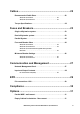
Contents Product Overview............................................................ 1 UPS for up to 2 battery modules . . . . . . . . . . . . . . . . . . . . . . . . . . . . 1 UPS for up to 4 battery modules . . . . . . . . . . . . . . . . . . . . . . . . . . . . 1 Features . . . . . . . . . . . . . . . . . . . . . . . . . . . . . . . . . . . . . . . . . . . . . . . . . 1 Availability . . . . . . . . . . . . . . . . . . . . . . . . . . . . . . . . . . . . . . . . . . . . . . 1 Serviceability . . . . . .
Batteries ......................................................................... 11 Specifications . . . . . . . . . . . . . . . . . . . . . . . . . . . . . . . . . . . . . . . . . . . 11 Efficiency DC to AC . . . . . . . . . . . . . . . . . . . . . . . . . . . . . . . . . . . . . . 11 380 V, 400 V, and 415 V . . . . . . . . . . . . . . . . . . . . . . . . . . . . . . . . . . . 11 380 V, 400 V, and 415 V 3:1 . . . . . . . . . . . . . . . . . . . . . . . . . . . . . . . .
Cables .............................................................................22 Recommended Cable Sizes . . . . . . . . . . . . . . . . . . . . . . . . . . . . . . . .22 380 V, 400 V, and 415 V . . . . . . . . . . . . . . . . . . . . . . . . . . . . . . . . . . . 22 380 V, 400 V, and 415 V 3:1 . . . . . . . . . . . . . . . . . . . . . . . . . . . . . . . . 22 Torque Specifications . . . . . . . . . . . . . . . . . . . . . . . . . . . . . . . . . . . . .22 Fuses and Breakers.........................
Empty Cabinet for Transformer - floor-mount . . . . . . . . . . . . . . . . . 31 Parallel Capabilities....................................................... 32 Communication cables . . . . . . . . . . . . . . . . . . . . . . . . . . . . . . . . . . . 32 Schematic of the PBus cables layout . . . . . . . . . . . . . . . . . . . . . . . 32 System arrangements . . . . . . . . . . . . . . . . . . . . . . . . . . . . . . . . . . . . 32 Overview of Power Connections. . . . . . . . . . . . . . . . . . . . . . .
Product Overview The MGE Galaxy 3500 UPS is available in the following models: UPS for up to 2 battery modules • MGE Galaxy 3500 10 kVA 400 V • MGE Galaxy 3500 15 kVA 400 V • MGE Galaxy 3500 15 kVA 400 V 3:1 • MGE Galaxy 3500 20 kVA 400 V • MGE Galaxy 3500 20 kVA 400 V 3:1 UPS for up to 4 battery modules • MGE Galaxy 3500 10 kVA 400 V • MGE Galaxy 3500 15 kVA 400 V • MGE Galaxy 3500 15 kVA 400 V 3:1 • MGE Galaxy 3500 20 kVA 400 V • MGE Galaxy 3500 20 kVA 400 V 3:1 • MGE Galaxy 3500 30 kVA 400 V • MGE Gala
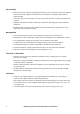
Serviceability • Batteries that can be replaced by qualified personnel: Increases availability by allowing qualified personnel to perform upgrades and replacement of the batteries reducing the Mean Time To Repair (MTTR) • Automatic self-test: Periodic battery self-test ensures early detection of a battery that needs to be replaced • Shippable with modules installed: Enables pre-installation UPS staging and testing and faster installation • Modular design: Provides fast serviceability and reduced maintenance
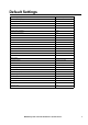
Default Settings System settings (only updated when in load disconnect) Default setting Nominal output voltage (ph-ph) 380/400/415 V Frequency 50 Hz Frequency self-detect mode Auto Frequency range ±10 Hz Frequency slew rate 1 Hz/s Generator charge percentage 100% Cyclic charge mode enabled Off Auto start On Parallel UPS number 1 No.
AC Input Specifications 380 V, 400 V, and 415 V 10 kVA 15 kVA 20 kVA 30 kVA 40 kVA 380 V 400 V 415 V 380 V 400 V 415 V 380 V 400 V 415 V 380 V 400 V 415 V 380 V 400 V 415 V Connection type 5-wire (3PH + N + PE) Input frequency (Hz) 40-70 I thd < 5% at full load Nom input current (A) 13.0 12.3 11.9 19.4 18.5 17.8 26.0 24.7 23.8 38.6 36.7 35.3 51.7 49.1 47.3 Max input current (A) 14.3 13.5 13.1 21.4 20.3 19.6 28.6 27.2 26.2 42.5 40.3 38.9 56.8 54.0 52.
AC Output Specifications 380 V, 400 V, and 415 V 10 kVA 15 kVA 20 kVA 30 kVA 40 kVA 380 V 400 V 415 V 380 V 400 V 415 V 380 V 400 V 415 V 380 V 400 V 415 V 380 V 400 V 415 V Connection type 5-wire (3PH + N + PE) Output capacity 150% for 1 minute (normal operation) 125% for 10 minutes (normal operation) 150% for 1 minute (battery operation) 125% for 10 minutes (battery operation) 110% continuous (bypass operation) 800% for 500 ms (bypass operation) Voltage tolerance +/- 20% (304-477 V) at full load
Efficiency Note: The below figures are for the 3:3 version only. System 25% load 50% load 75% load 100% load 10 kVA 400 V 91.9 94.4 94.7 94.5 15 kVA 400 V 93.2 95.4 95.7 95.7 20 kVA 400 V 94.4 95.7 95.7 95.6 30 kVA 400 V 94 95.6 95.8 95.8 40 kVA 400 V 94.9 95.8 95.8 95.6 Note: Low line is 348 V and high line is 452 V (+/- 13%).
20 kVA 400 V 98,0 96,0 94,0 Efficiency [%] 92,0 Low line voltage 90,0 Nominal line voltage High line voltage 88,0 Battery operation 86,0 84,0 82,0 80,0 0 20 40 60 80 100 Load [%] 30 kVA 400 V 98,0 96,0 94,0 Efficiency [%] 92,0 Low line voltage 90,0 Nominal line voltage High line voltage 88,0 Battery operation 86,0 84,0 82,0 80,0 0 20 40 60 80 100 Load [%] 40 kVA 400 V 98,0 96,0 94,0 Efficiency [%] 92,0 Low line voltage 90,0 Nominal line voltage High line voltage 88,0 Bat
Derating due to Load Power Factor .8 =0 . 7 sf 0 Co f = s Co Co Co sf = s f 0. =0 6 .5 kW 1.00 0.75 0.50 LAGGING C Co osf = 0. sf =0 8 .7 LEADING 6 0. = sf =0.5 o C o sf C 0.25 kVAr kVAr -1.0 -0.8 -0.6 -0.4 -0.2 8 0 0.2 0.4 0.6 0.8 1.
Environmental General Temperature • Operating 0-40º C • Storage with batteries -15-45º C • Storage without batteries -30-70º C Humidity • Operating 0-95%, non-condensing • Storage 0-95%, non-condensing Elevation • Operating 0-1000 m: 100% load 1000-1500 m: 95% load 1500-2000 m: 91% load 2000-2500 m: 86% load 2500-3000 m: 82% load • Storage 0-15000 m Audible noise • At 70% load 10-15 kVA 208/220 V 20-30 kVA 208/220 V 10-20 kVA 380/400/415 V 30-40 kVA 380/400/415 V 42.3 dBA 46.2 dBA 42.
Heat Dissipation 380 V, 400 V, and 415 V 10 kVA 15 kVA 20 kVA 30 kVA 40 kVA Batteries Batteries fully charged charging Batteries Batteries fully charged charging Batteries Batteries fully charged charging Batteries Batteries fully charged charging Batteries Batteries fully charged charging 0.54 (1842) 0.77 (2620) 1.08 (3685) Heat dissipation 0.46 (1583) kw (BTU/hr) 0.54 (1856) 0.66 (2252) 0.93 (3166) 1.
Batteries Specifications 10-40 kVA 380/400/415 V Type VRLA Nominal voltage (VDC) +/- 192 Float voltage (VDC) +/- 219 End of discharge voltage (VDC) +/- 154 Battery current (at full load) 87.9 A at + 192 V Max. current (at end of discharge) 110.1 A at + 154 V Max. charging power 10 kVA: 800 15 kVA: 1200 20 kVA: 1600 30 kVA: 2400 40 kVA: 3200 5 hours Typical re-charge time End voltage 1.6-1.
Battery Run-Times (Minutes) - APC Battery Solution Note: “# of battery shelves” indicates the total number of populated battery shelves in the UPS and Battery Enclosure.
15 kVA 400 V typical performances Load kVA 1 3 6 9 12 15 1 n.a. n.a. n.a. n.a. n.a. n.a.
kVA 400 V typical performances Load kVA 2 4 8 12 16 20 1 n.a. n.a. n.a. n.a. n.a. n.a.
30 kVA 400 V typical performances Load kVA 2 6 12 18 24 30 1 n.a. n.a. n.a. n.a. n.a. n.a. 2 n.a. n.a. n.a. n.a. n.a. n.a.
40 kVA 400 V typical performances Load kVA 4 8 1 n.a. n.a. n.a. n.a. n.a. n.a. 2 n.a. n.a. n.a. n.a. n.a. n.a. 3 n.a. n.a. n.a. n.a. n.a. n.a.
Battery Run-Times - Non-Modular Batteries • The below battery run-times are based on high quality batteries from approved manufacturers • The run-times are based on high rate batteries designed for UPS systems • The run-times are intended as a guide only, and APC disclaim the responsibility for these runtimes 10 kVA Load % 120 20 hr rate Ah Approx. equivalent 10 hr rate Ah 40 50 60 70 80 90 100 7.2 6.
20 kVA Load % 120 Approx.
Battery Discharge Current 380 V, 400 V, and 415 V 10 kVA 15 kVA 20 kVA 30 kVA 40 kVA I bat @ Vbat nominal, 100% load 22 33 44 66 88 I bat @ Vbat min, 100% load 28 41 55 83 110 I bat @ Vbat min, 150% load 40 62 83 125 166 End of Discharge Voltage Volts per Cell End-of-Discharge Voltage 1.75 1.70 1.65 1.60 Discharge CA-rate 0 0.5 1.0 1.5 2.0 2.5 3.0 3.5 4.
AC Bypass Specifications 380 V, 400 V, and 415 V 10 kVA 15 kVA 20 kVA 30 kVA 40 kVA 380 V 400 V 415 V 380 V 400 V 415 V 380 V 400 V 415 V 380 V 400 V 415 V 380 V 400 V 415 V Connection type 5-wire (3PH + N + PE) Input frequency (Hz) 40-70 Nom input current (A) 15.2 14.4 13.9 22.8 21.7 20.9 30.4 28.9 27.8 45.6 43.3 41.7 60.
Physical Dimensions Enclosure net dimensions mm (in) Height 1499 (59) Depth - exclusive of the conduit box - inclusive of the conduit box 838 (33) 925 (36) Width - narrow - wide 356 (14) 523 (21) Weights 380 V, 400 V, and 415 V 380/400/415 V kg 380/400/415 V kg G35T10KH1B2S 245 G35T10KH2B2S 336 G35T10KH1B4S 382 G35T10KH2B4S 474 G35T10KH3B4S 566 G35T10KH4B4S 657 G35T15KH2B2S 433 G35T15KH2B4S 474 G35T15KH3B4S 566 G35T15KH4B4S 657 G35T20KH2B2S 433 G35T20KH2B4S 474 G35T20KH3B
Cables Recommended Cable Sizes Note: Refer to IEC 60364-5-52 for installation methods. The recommended cable sizes are for installation method B2 and based on an environment with an ambient temperature of 30° C. Note: Temperature ratings of conductors: 70°C. Use only copper conductors and PVC isolated cables. 380 V, 400 V, and 415 V 10 kVA 15 kVA 20 kVA 30 kVA 40 kVA Utility/mains input 2.5 mm2 6 mm2 10 mm2 16 mm2 25 mm2 Static bypass input 2.
Fuses and Breakers Single utility/mains system Q1: Utility input Q3: Manual Bypass Q2: UPS output MBS: Mechanical bypass switch Dual utility/mains system Q1: UPS input Q5: Static bypass input Q2: UPS output Q3: Manual bypass MBS: Mechanical bypass switch MGE Galaxy 3500 10-40 kVA 380/400/415 V Quick Reference 23
Parallel System Q3 Q4 Q5B Q2B Q1B UPS B XR Battery Enclosure (optional) Q5A Q2A Q1A UPS A XR Battery Enclosure (optional) Q1: Utility input Q4: System output Q2: UPS output Q5: Static bypass input Q3: Manual bypass Fuse and Breaker Sizes 380 V, 400 V, and 415 V 10 kVA 15 kVA 20 kVA 30 kVA 40 kVA (A)1 16 25 35 50 63 Bypass input Q5 (A) 16 25 35 50 63 Output Q2 (A) 16 25 35 50 63 15 kVA 20 kVA 30 kVA 40 kVA 25 35 50 63 75 100 150 200 75 100 150 200 Mains inp
380 V, 400 V, and 415 V Parallel system with up to three UPS units Note: It is not possible to run the 3:1 version in parallel. Q3 and Q4 in capacity systems. Units in parallel 10 kVA 15 kVA 20 kVA 30 kVA 40 kVA 2 35 A 50 A 63 A 100 A 125 A 3 50 A 80 A 100 A 160 A 200 A 4 63 A 100 A 200 A 200 A 250 A Q3 and Q4 in redundant systems (n+1).
Minimum Breaker Settings 380 V, 400 V, and 415 V 800% overload bypass operation 150% overload normal/battery operation 125% overload normal/battery operation 500 ms 60 s 10 min. Mains input -1 - - 16.4 A Bypass input 121.5 A - - 16.7 A Output 121.5 A 22.8 A 19 A 16.7 A Mains input -1 - - 24.6 A Bypass input 182 A - - 25.1 A Output 182 A 34.2 A 25.4 A 25.1 A Mains input -1 - - 32.5 A Bypass input 244 A - - 33.4 A Output 244 A 45.6 A 38 A 33.
Communication and Management Network Management Card The system is equipped with one network management card for remote monitoring and control of an individual UPS by connecting it directly to the network.
Input and Output Contacts Pin connections J106 (UPS) J106 Charging control switch Q3 switch J200 (XR Batteries) Pins 7 and 8 are for external charge control. When 7 and 8 are closed, the UPS charges batteries with a pre-defined percentage (0-25-50-75-100%) of the maximum charging power. To be used in generator applications, or if special codes require control of charging. When Q3 is closed, signals are fed back to the UPS controller.
EPO Pin connections J108 1: Dry Contacts Normally Open J108 EPO circuit J108 +24 V EPO circuit 0V EPO is activated when pin 1 is connected to pins 3 and 5. Connections: 2-4-6, 3-5 and 1 ( ) 2: +24 V Normally Open EPO is activated when an isolated SELV 24 VDC voltage is supplied on pin 1 with reference to pin 2. Connections: 3-5 and 4-6. 3: Dry Contacts Normally Closed J108 EPO is activated when a connection from pin 3 to pin 5 is opened. Connections: 4-6.
Compliance Regulatory Approvals Directives for CE marking 89/336/EDC 73/237/EEC Safety EN/IEC62040-1-1 UL1778 EMC EN50091-2/IEC62040-2 FCC15A Performance EN/IEC62040-3 Electromagnetic compatibility (EMC) EN/IEC 61000-4-2 level 3, performance criteria A EN/IEC 61000-4-3 level 2, performance criteria A EN/IEC 61000-4-4 level 2, performance criteria A EN/IEC 61000-4-5 level 3, performance criteria A 30 MGE Galaxy 3500 10-40 kVA 380/400/415 V Quick Reference
Options Parallel MBP - wall-mount • For a line-up-and-match solution with up to three UPS units in parallel • Two versions for 10-20 kVA and 30-40 kVA UPS units • Two ratings: 60 kVA and 120 kVA • Top or bottom cable entry • Including three communication boards • With lamps for status indication Empty Cabinet for batteries - floor-mount • For a line-up-and-match solution for 3rd party batteries • Up to eight trays for 32 customer-supplied batteries (16 on + bus and 16 and - bus).
Parallel Capabilities Up to four UPS units can be connected in parallel via the Parallel Communication Kit. Parallel Communication Box Communication cables Schematic of the PBus cables layout UPS 1 TERMINATORS UPS 2 PBus1 PBus2 UPS 3 PBus1 PBus2 UPS 4 PBus1 PBus2 1A 2A 1A 2A 1A 2A 1A 2A 1B 2B 1B 2B 1B 2B 1B 2B PBus1 PBus2 TERMINATORS Note: If the configuration consists of only two UPSs, the terminators must be installed in UPS 2.
Overview of Power Connections The below diagrams shows a parallel system with three UPS units and XR Battery Enclosures.
APC Worldwide Customer Support Customer support for this or any other APC product is available at no charge in any of the following ways: • Visit the APC Web site to access documents in the APC Knowledge Base and to submit customer support requests. – www.apc.com (Corporate Headquarters) Connect to localized APC Web sites for specific countries, each of which provides customer support information. – www.apc.com/support/ Global support searching APC Knowledge Base and using e-support.