Network Management Card & Modbus/Jbus 66123 User Manual Network Management Teleservice Card 66124 User Manual For Galaxy 7000 UPS and SSC unit Network Management Card & Modbus/Jbus Network Management Teleservice Card APC by Schneider Electric www.apc.
Contents 1 MGE GALAXY 7000 NETWORK MANAGEMENT CARD PRESENTATION......................................................................................... 5 1.1 CONNECTING THE UPS TO THE ETHERNET NETWORK ................................................................................................................................. 6 1.2 PROTECTION OF THE COMPUTERS / SERVERS....................................................................................................................................
6 SUPERVISION AND ADMINISTRATION BY BROWSER ................................................................................................................... 21 6.1 OPTIMISING THE PERFORMANCE OF YOUR BROWSER ................................................................................................................................ 21 6.2 UPS .............................................................................................................................................................
9.4 CHOICE 4: RETURN TO DEFAULT CONFIGURATION ................................................................................................................................... 64 10 MODBUS/JBUS INSTALLATION & USE............................................................................................................................................ 65 10.1 INSTALLATION ...................................................................................................................................
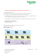
1 MGE Galaxy 7000 Network Management card presentation MGE Galaxy 7000 Network Solution: provides information on events concerning the supply of power to the computers connected to your computer network, carries out automatic shutdown of computer systems and monitors all the UPSs connected to the network.
1.1 Connecting the UPS to the Ethernet network This function can be performed through the network Cards inserted in the UPS (Network Management Card).
1.3 Supervision of the UPSs over the network Depending on your needs, you can either use: Your Internet browser to monitor each UPS, as Management Card includes a Web server. Your company’s standard Network Management System (HP-Openview, CA Unicenter, HP Insight Manager, IBM Tivoli Netview). To simplify integration of MGE Galaxy 7000 UPSs, you can use one of the Network Management System Kits for MGE devices. These kits are available on the Management Pac 2 CD-ROM.
1.4 Direct sending of E-mail When a UPS event occurs, the Network Management Card can directly notify up to 4 intranet or extranet addresses by e-mail (see E-mail Notification and E-mail message settings) 1.5 Sending text messages (SMS) The card offers the possibility of redirecting UPS alarms to an e-mail server. The format of these e-mails is compatible with mobile telephone e-mail/SMS transfer systems proposed by ISPs. The format to be used depends on the service provider. For example, sms.
2 Technical data 2.1 Hardware characteristics Dimensions Dimensions (L x l x H) 132 x 66 x 42 mm Weight (gr) 70 g. Storage Storage temperature -10°C to 70°C Ambient conditions Operating temperature 0°C to 40°C Ambient humidity 90% RH max without condensation RoHS 100% compatible 2.
2.4 Administration Up to 35 workstations protected by Network Shutdown Modules - Central or local configuration. Up to 5 browsers connected at the same time (3 in SSL). • Minimum recommended browser versions: Internet Explorer 6.x / 7.0, Mozilla Firefox 1.5 / 2.0 / 3.0 E-mail sending configurable according to UPS alarms and transmission of a periodical report. Automatic data and time adjustment via NTP server. Protection by encrypted password. Protection by secure SSL connection.
2.7 MIB (Management Information Base) Compatible with MIB MGE V1.8 adapted for Galaxy 7000. The list of objects managed can be found in the chapter 8.2. 2.8 Modbus/Jbus for INMC 66123 The Modbus/Jbus hexadecimal (MODBUS RTU) communication protocol is used in slave mode. The system provides a communication channel with an RS485 or RS232 interface. Note: 2 wires or 4 wires RS485 link are available. Warning: RS232 and RS485 communication ports cannot be used together.
2.10 Default parameters Function Parameter Default value Possible value Network IP address 172.17.16.16 Network IP address System Subnet mask 255.255.0.0 Network IP address Gateway Address 0.0.0.0 Network IP address BOOTP/DHCP Enabled Active / Deactivated Firmware Upload Enabled Active / Deactivated SMTP server smtpserver 49 characters maximum UPS Contact Computer Room Manager 49 characters maximum UPS Location Computer Room 31 characters maximum History log interval (sec.
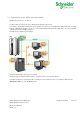
3 Installation Network Management Card & Modbus/Jbus (INMC 66123) 3.1 Unpacking and check on contents The installation kit contents: A Network Management Card & Modbus/Jbus (66123) A serial communication cable for configuration (3402226700) Installation manual (34022308) 3.2 Indications Network Management Card & Modbus/Jbus Network Management Teleservice Card APC by Schneider Electric www.apc.
Ethernet port LED Colour Activity Description ACT Green ◗ Off ◗ On ◗ ◗ ◗ Flashing ◗ ◗ Off On 100M Orange ◗ ◗ ◗ Card not connected to the network. Card connected to the network but without activity Port is active in receiving / transmission Port operating at 10Mbits/s. Port operating at 100Mbits/s. Service port (Settings/Sensor) LED Colour Activity Description UPS Data Green ◗ ◗ Off On ◗ ◗ ◗ ◗ Flashing Card startup in progress.
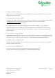
4 Installation Network Management Teleservice Card (NMTC 66124) 4.1 Unpacking and check on contents The installation kit contents: A Network Management Teleservice Card (66124) A serial communication cable for configuration (3402226700) One phone cable for teleservice (3402226800) One installation manual (34003976EN) 4.2 Indications Network Management Card & Modbus/Jbus Network Management Teleservice Card APC by Schneider Electric www.apc.
Ethernet port LED Colour Activity Description ACT Green ◗ Off ◗ On ◗ ◗ ◗ Flashing ◗ ◗ Off On 100M Orange ◗ ◗ ◗ Card not connected to the network. Card connected to the network but without activity Port is active in receiving / transmission Port operating at 10Mbits/s. Port operating at 100Mbits/s. Service port (Settings/Sensor) LED Colour Activity Description UPS Data Green ◗ ◗ Off On ◗ ◗ ◗ ◗ Flashing Card startup in progress.
It is connected to the Service port (Settings/Sensor) directly on the Network Management Card with a standard Ethernet cable (20 meters maximum). Recognition is automatic. Supervision and configuration are performed via a menu that can be accessed directly from the home page. 4.5 Line Phone Port Telephone connexion for the teleservice application. Network Management Card & Modbus/Jbus Network Management Teleservice Card APC by Schneider Electric www.apc.
5 Configuration 5.1 Configure IP parameters Once the card has started: Connect one end of the cable (3402226700) to the Service port. If the environment sensor was previously connected, the card must be restarted in order to access the configuration menu. Connect the other end of the cable to the COM port (IOIOI) of a PC.
5.1.1 Your network is equipped with a DHCP server The card is configured by default with this service activated. The card automatically collects IP parameters.
5.1.2 Your network is not equipped with a DHCP server In the main menu enter 2, then 2 again. The menu is displayed: Follow the instructions and enter the static IP parameters. At the end of the menu, wait for the "Done" message to be displayed indicating that the IP parameters have been saved.
6 Supervision and administration by browser On a computer equipped with a Web browser (Internet Explorer, FireFox or Netscape recommended), enter the address initialised previously in the Installation chapter (e.g. http://172.17.16.16.) The "UPS properties" home page is displayed. 6.1 Optimising the performance of your browser To view status changes on the UPS in real time, the browser must be configured so that it automatically refreshes all the objects on the current page.
6.2.1.1 "UPS" zone: general information on the UPS. Indication of the picture and generic name of the UPS range Computer room: Customised name of your system. You can change this name on the "System" page. UPS status icon : The various icons showing the status of the UPS are: Normal operation Alarm present. This icon links directly to the alarm page. Loss of communication with the UPS Animated synoptic: An animated synoptic gives a global overview of the UPS current operating mode.
UPS without automatic bypass SSC Static Switch Cabinet Note: In case of loss of communication with the UPS, all the elements of the synoptic are grey.
Battery : Remaining capacity > 50% Remaining capacity < 50% Battery to be checked (battery test result) Battery Output Flow : DC to AC converter powered by battery DC to AC converter not powered by battery DC to AC Converter Input flow : Energy flow present No energy flow DC to AC Converter : Powered Not powered Internal failure DC to AC Converter Output : Energy flow present No energy flow AC Bypass Input : In tolerances Out of tolerances AC Automatic Bypass Flow : Energy flow present No energy fl
AC Automatic Bypass Status : Powered Not powered Internal failure AC Manual Bypass Flow : Energy flow present No energy flow AC Manual Bypass Status : Open Closed AC Output Flow : Energy flow present No energy flow AC Output : Load protected Load not protected Network Management Card & Modbus/Jbus Network Management Teleservice Card APC by Schneider Electric www.apc.
6.2.1.2 "UPS measurements” Boxes showing measurements appear when synoptic elements are hovered by the pointer. See example below. These measurements are available for AC to DC converter, Battery, DC to AC converter and automatic bypass. The measurements available in these boxes depend on the UPS range. Network Management Card & Modbus/Jbus Network Management Teleservice Card APC by Schneider Electric www.apc.
6.2.1.3 "UPS status" zone: Essential information "Active sources": (available on parallel or modular UPS) x UPS + y UPS redundant : x indicates the minimal number of UPS necessary to power the load, y indicates the number of UPS in redundancy. An alarm can be generated if the number of UPS in redundancy is less than a configurable threshold. See UPS modules section.
6.2.1.4 Viewing the alarms Click on "Alarm Table" scroll list to view the list of current alarms. The table of managed alarms is included in the appendix. The level of the alarms appears like below: Critical Warning Unknown Alarm table for standard UPS Network Management Card & Modbus/Jbus Network Management Teleservice Card APC by Schneider Electric www.apc.
6.2.1.5 Viewing the “About your UPS” window Click on "About your UPS" scroll list to view the information about the UPS and the card. Network Management Card & Modbus/Jbus Network Management Teleservice Card APC by Schneider Electric www.apc.
Network Management Card & Modbus/Jbus Network Management Teleservice Card APC by Schneider Electric www.apc.
6.2.2 On-line help On-line contextual help in English is available at the top of each page by clicking on the Help link, which is always located on the top right corner. The navigation menu of the on-line help is identical to that of the card's pages. The Help page always opens a new window. Network Management Card & Modbus/Jbus Network Management Teleservice Card APC by Schneider Electric www.apc.
6.2.3 Shutdown parameters The menu Shutdown Parameters is not present with a UPS Static Switch Cabinet. This page enables viewing and configuration of UPS operating parameters in battery mode and for power restoration. This menu is accessible only after entering the "Login" and "Password". The following screen is proposed automatically: The default login and password are: MGEUPS Each field accepts up to 10 characters max. After the login and password are entered, they remain active for 5 minutes.
Click on the "Shutdown parameters" section in the menu to see the list of parameters. When you click the Show advanced parameters option, extra parameters are displayed. These parameters enable, in particular, adjustment of certain thresholds related to the percentage of remaining battery charge level. The Output column enables the output to be named (maximum 20 characters, "Master" by default).
6.2.
6.2.5 Event log Click on "Event Log" in the menu "Save log" enables all saved values to be opened or saved in CSV format. (compatible with Excel type spreadsheets) "Clear log" enables deletion of all records. The administrator must enter his/her login / password to validate this action. The table of managed alarms is included in the appendix. Network Management Card & Modbus/Jbus Network Management Teleservice Card APC by Schneider Electric www.apc.
6.2.6 System log Click on "System log". in the menu "Save log" enables all saved values to be opened or saved in CSV format. (compatible with Excel type spreadsheets) "Clear log" enables deletion of all records. The administrator must enter his/her login / password to validate this action. The table of managed alarms is included in the appendix. Network Management Card & Modbus/Jbus Network Management Teleservice Card APC by Schneider Electric www.apc.
6.3 Notification 6.3.1 Email Notification The card offers the possibility of redirecting UPS alarms to an e-mail server. The format of these e-mails is compatible with mobile telephone transfer systems using text messages (SMS).
Recipient List: On the left side of this page, up to four recipients can be configured to receive e-mails from the card. Each addressee has its own trigger events, selected from the right side of the page, for which an e-mail is sent. The card’s log indicates e-mail transmission errors Each recipient is configured with the following parameters Recipient: (Field is limited to 49 characters) this is the e-mail address of the person or department to receive the e-mail. The default value is recipientx@domain.
6.3.2 E-mail Message Settings This page enables customisation of the content of the messages received by recipients of e-mails sent by the card. Customisation is common to the four recipients that can be notified (see E-mail notification). Sender (59 characters maximum) identifies the source of the message. The default value is ups@domain.com. This field is free.
The body of the e-mail sent is composed of: - Message text, which is free text. - The date and time of the event, as saved in the log. - URL of the card, enabling a direct link with the card to be established. - Attachments, as configured for the e-mail recipients. - Duplication of the subject, as configured. 6.4 Configuration The parameters of this menu can only be modified after entering the "Login" and "Password".
6.4.1 Network settings Click on "Network" in the menu. This menu enables the administrator to configure the network parameters of the card and authorisation of the remote upgrade of the embedded system. IP Address: The IP address of the card (e.g.: 172.17.22.252). Subnet Mask: The mask of the sub-network of your network (e.g.: 255.255.255.0). Gateway Address: Indicate the IP address of the gateway to access the stations located outside the card’s subnet (e.g.: 172.17.17.1).
BOOTP/DHCP: Authorises (choose "Enabled") configuration of network parameters with your BootP/DHCP server when the card is booted. Mode of card operation with server: After each startup, the card makes 5 attempts to recover the network parameters. If no response is received from the server, the card boots with the last saved parameters from the previous start. These parameters are those shown on the page.
6.4.2 System Click on "System" in the menu. This menu enables the customisation of the information on the UPS properties pages. UPS Contact: This text field is limited to 49 characters. Enter the name of the person responsible for UPS administration at IT network level and/or electrical maintenance. This field does not appear on any other Web page. By default, its value is "Computer Room Manager".
6.4.3 Notified Applications Click on "Notified Applications" in the menu. Security: The administrator has to enter his/her login/password in order to view this information. This menu enables: The addition of the supervision stations receiving traps and configuration of the trap type. To list all the Notified Applications and the main parameters. To test the operation of notified applications by simulating power loss by sending a real shutdown sequence. Up to 50 destinations can be managed by the card.
Configuration: shows where the parameters of the Network Shutdown Module come from: Local (coming from the application) or Central (coming from the card). The Central shutdown configuration is available by clicking on the Configuration link. Shutdown duration: the shutdown duration necessary to properly shutdown the computer. Shutdown after: the time available to the user from the power failure until the launch of the shutoff sequence of the UPS and equipment. This parameter is optional.
6.4.4 Central shutdown configuration The menu Shutdown Parameters is not present with a UPS Static Switch Cabinet. Click on "Notified Applications" in the menu, then "Configuration". This page is used to define either the "shutdown" or the "notification" settings used by the Network Shutdown Modules that connect to Network Management Card. These settings are used by the Network Shutdown Modules if they are in central-configuration mode or if their configuration is not valid.
6.4.5 Access control Click on "Access Control" in the menu. To access this page, the login and password are systematically requested if they have not already been entered. This menu enables configuration of the different parameters enabling secure access to the card via a browser or SNMP. Login: This text field is limited to 10 characters. - Enables secure access and modification of pages. Default value "MGEUPS". Change / Confirm password: This text field is limited to 10 characters.
Export settings to file: Enables exportation ("Download" button) and saving of card configuration information. Import settings from file: Enables selection of a configuration file ("Browse" button) and uploading ("Upload" button) of card configuration information Network Management Card & Modbus/Jbus Network Management Teleservice Card APC by Schneider Electric www.apc.
6.4.6 Date and time Click on "Date and Time" in the menu. This menu enables initialisation of the date and time of the card in three different ways. The date format is always of year/month/day type Set manually: Enables initialisation of the date and time of the card, with the values entered in the Date and Time fields. This update is made after clicking on the "Save" button. Maximum drift is +/- 2 min.
6.4.7 Firmware upload Click on "Firmware Upload" in the menu. This menu enables a new firmware version to be uploaded To upload a new version of the card's firmware, select the file to be loaded using the "Browse…" button and click Upload. Do not interrupt the operation before the card displays the following screen: Network Management Card & Modbus/Jbus Network Management Teleservice Card APC by Schneider Electric www.apc.
6.5 Environment Sensor (option) The environment sensor (66846) is an option that enables temperature and humidity to be measured, and indication of the position of two external contacts. It is connected with a standard network cable to the Card Settings port of the Network Management Card. The card automatically detects sensor presence.
6.5.2 Environment Status For both measurements, a graduated gauge proposes the following functions: The cursor indicates the current value. Two red zones to the left and right represent the high and low thresholds that can be set on the Environment Settings page. When the measured value enters one of these zones, an alarm can be notified (see Notification parameter in the Environment Settings page).
6.5.3 Environment Settings The environment sensor measures temperature, humidity and gives the status of the 2 contacts (used for door, alarms or generator unit). The temperature and humidity thresholds can be adjusted and can trigger notification and correct shutdown of the protected system. The Sensor name is the function name given to the sensor, usually it enables location of the sensor. Temperature: Choose the temperature unit (°C or °F) from the s election box.
Low threshold: If this value is exceeded, a notification is sent if this is validated. The default value is 5%. Hysteresis must be set to prevent multiple notifications if humidity fluctuates around a threshold. The default value is 5%. The high alarm disappears when the value drops below the High threshold - Hysteresis value The low alarm disappears when the value returns above the Low threshold - Hysteresis value Input #1 and Input #2: Enter an identifier corresponding to the acquired contact (e.g.
6.5.4 Log The two environment sensor measurements: Temperature and Humidity are recorded at an interval defined by the Environment log interval in the System settings page. By default, this period is 300 seconds. Each measurement is dated and stored in the log of the UPS’s communication card. The size of log files is limited by a time indexing system. The user can Save the log on his/her workstation at any time, in a CSV format file.
7 Server protection 7.1 Set-up of the shutdown parameters The Network Shutdown Module, on protected server boot, subscribes itself automatically to notified applications list and sends its essential data: IP Address or hostname of the server on which it is installed: So that the card can inform it of power events.
7.2 Shutdown criteria managed by the Network Management Card During an extended power failure, three criteria may cause the server shutdown procedure to be initiated. If several criteria are selected, (See page Shutdown parameters), the first criterion encountered will launch the shutdown procedure.
7.2.2 Initiating the shutdown procedure when the battery autonomy ratio is lower than: (If remaining time ratio under) When the card detects that the remaining time ratio (percentage) is less than the configured level, the shutdown sequence is started. By default, this value is set at 20%. This ratio is equal in % to : Current autonomy time / Autonomy time announced at the beginning of the UPS on battery sequence Note: The UPS already manages an equivalent parameter for the end of backup pre-alarm.
8 Teleservice 8.1.1 Teleservice procedure ◗ Install the Network Management Teleservice Card kit using the present manual. ◗ Contact your customer service for start the Teleservice option. ◗ Send the form to your Teleservice center (by Fax or Internet). ◗ Your center will activate this service. ◗ Then you will receive an acknowledgement of receipt. The information form must be sent back in order to trigger remote monitoring of your equipment.
Network Management Card & Modbus/Jbus Network Management Teleservice Card APC by Schneider Electric www.apc.
9 Configuration via RS232 Use the cord supplied with the card. Connect the card to a computer equipped with a hyperterminal type emulator. The serial link must be set at 9600 baud, 8 bits, no parity, 1 stop bit, and without flow control. Check that UPS power is on. Enter the MGEUPS or mgeups password (non modifiable). The menu is in English only. 9.
9.2 Choice 2: Network Configuration Use this function to access network settings. ----------------------------------------------------------------------------Network settings ----------------------------------------------------------------------------1 : Read Network settings 2 : Modify Network settings 3 : Set Ethernet speed 0 : Exit ----------------------------------------------------------------------------- 9.2.
9.2.3 Choice 3: Set Ethernet speed Enables the modification of the network speed Set the Ethernet speed : [1 : Automatic, 2 : 10 MBit] 1 New Ethernet speed : Automatic Wait during the new setting is saved ... Reset the card to take into account the new configuration. The card must be restarted in order for the new parameters to be taken into account. 9.
9.
10 Modbus/Jbus installation & use 10.1 Installation 10.1.1 RS232 link configuration and connection Set the SA2 switches like below: The next figure shows the details of the connection in RS232 mode: Pin number Function 1 Received data (input) 2 Not connected 3 Network Management Card & Modbus/Jbus Network Management Teleservice Card APC by Schneider Electric www.apc.
10.1.2 RS485 link configuration and connection 10.1.2.1 RS485 connection Normally, the master of the network sets the polarity of the line. The INMC card is a slave equipment and don’t have polarisation resistor. The two ends of the line must be terminated. Allow for 1 or 2 terminators to avoid mismatching the line when any equipment at the end of the line is disconnected.
The settings of the RS485 link are made through the SA1 switches: SA1 description: 1: Polarization + to T2: Polarization - to T+ 3: Link termination between T- to R- (2 wires configuration) if set to ON 4: Connection T- to R- (2 wires configuration) if set to ON 5: Connection T+ to R+ (2 wires configuration) if set to ON 6: Polarization + to R7: Polarization - to R+ 8: Link termination between R+ and R- if set to ON Network Management Card & Modbus/Jbus Network Management Teleservice Card APC by Schneide
10.1.2.2 RS485 link configuration for 2 wires connexion Set the SA2 switches like below to set the RS485 mode: Set the SA1 switches to select the two wires configuration with no termination: Network Management Card & Modbus/Jbus Network Management Teleservice Card APC by Schneider Electric www.apc.
Set the SA1 switches to select the two wires configuration with termination: The next figure gives a typical bus structure in the two wires configuration: Network Management Card & Modbus/Jbus Network Management Teleservice Card APC by Schneider Electric www.apc.
10.1.2.3 RS485 link configuration for 4 wires connexion Set the SA2 switches like below: Set the SA1 switches to select the four wires configuration with no termination: Network Management Card & Modbus/Jbus Network Management Teleservice Card APC by Schneider Electric www.apc.
Set the SA1 switches to select the four wires configuration with termination: The next figure gives a typical bus structure in the four wires configuration: Network Management Card & Modbus/Jbus Network Management Teleservice Card APC by Schneider Electric www.apc.
10.1.3 Configuration of the JBUS/MODBUS communication parameters Connect the card to a computer equipped with a Hyper terminal type emulator. The serial link must be set at 9600 baud, 8 bits, no parity, 1 stop bit, and without flow control. Check that UPS power is on. Enter the MGEUPS or mgeups password (non modifiable).
10.1.3.1 Choice 1: Display Jbus settings Enables reading of the card's Jbus settings Jbus configuration : Slave number : 7 Speed : 9600 bds Data : 8 bits stop bit : 1 Parity : None 10.1.3.2 Choice 2: Modify Jbus settings Enables the modification of Jbus settings.
10.1.3.4 Choice 4: Reset Jbus diagnostics Reset the Jbus diagnostic counters. 10.1.3.5 Choice 5: Return to Jbus Default Configuration Returns to the Jbus default configuration (0x01, 9600, 8, 1, none) Wait during Jbus configuration returns to default ... Jbus Configuration has been set to default one. 10.1.3.
10.2 Additional Web pages The INMC card Jbus parameters could be set through the next page: Network Management Card & Modbus/Jbus Network Management Teleservice Card APC by Schneider Electric www.apc.
10.3 Modbus register map 10.3.
Status to Status description Status to 1 0 Word (hex) Bit (0-15) Overlaptransfert fault on SSC No yes 45 11 Maintenance position No yes 46 1 AC bypass overload (Nota 7) No yes 46 5 AC bypass thermal overload (Nota 7) No yes 46 6 AC bypass fault (Nota 7) No yes 46 7 AC bypass frequency out of tolerance (Nota 7) No yes 46 9 AC bypass voltage out of tolerance (Nota 7) No yes 46 A Phase AC bypass out of tolerance (Nota 7) No yes 46 B AC bypass sitch (Q4S) Open Clo
10.3.
Description of the physical quantity Word (hex) Unit Output frequency 141 dHz Battery backup time (Nota 1) 149 Min Battery temperature (Nota 1) 14A °C Battery charging level (Nota 1) 14B % U AC normal (phase 1) (Nota 1) 150 V U AC normal (phase 2) (Nota 1) 151 V U AC normal (phase 3) (Nota 1) 152 V Number of battery block (Nota 1) 153 - Total battery capacity (Nota 1) 154 Ah Nominal Apparent Power 209 kVA Nominal battery voltage (Nota 1) 213 V Nota1 : This Information is
10.3.4.2 Sensor Measurements table Description of the physical quantity Word (hex) Unit Temperature measure 180 °C Maximum temperature 181 °C Minimum temperature (°C) 184 °C Humidity measure (%) 187 % Maximum humidity (%) 188 % Minimum humidity (%) 18B % Network Management Card & Modbus/Jbus Network Management Teleservice Card APC by Schneider Electric www.apc.
10.3.4.
11 Appendices 11.1 Tables of alarms and events 11.1.1 Table of alarms and UPS events List of time dated alarms Alarm on Alarm off No Battery Battery present Battery temperature fault Battery temperature OK Battery charger fault Battery charger OK Battery fault Battery OK End of Warranty LCM message OK Contact MGE http://www.mgeups.com/lcm End of battery life LCM message OK Contacter MGE http://www.mgeups.com/lcm End of life of the wearing parts LCM message OK Contacter MGE http://www.
Inverter fault Inverter OK Inverter overload Inverter load OK Inverter thermal overload Inverter load OK Load not protected - On Automatic Bypass Load protected - Return from Bypass Load short circuit Load OK Load not powered Load powered Protection Lost Protection OK Emergency button ON Emergency button OFF Fan fault Fan OK Redundancy Lost Redundancy OK Low battery Battery OK UPS communication failed UPS communication restored UPS data base not available UPS data base OK UPS on ba
11.1.
11.2 SNMP objects 11.2.1 MGE MIB The NMC card implement reduce MGEUPS MIB, with the objects bellow managed. Access to the MGE MIB is 1.3.6.1.4.1.705.1. MIB object SNMP Format Add.
mgoutputFrequency_2 deciHz {7,2,1,3,2,0} mgoutputFrequency_3 deciHz {7,2,1,3,3,0} mgoutputLoadPerPhase_1 % {7,2,1,4,1,0} mgoutputLoadPerPhase_2 % {7,2,1,4,2,0} mgoutputLoadPerPhase_3 % {7,2,1,4,3,0} mgoutputCurrent_1 deciAmps {7,2,1,5,1,0} mgoutputCurrent_2 deciAmps {7,2,1,5,2,0} mgoutputCurrent_3 deciAmps {7,2,1,5,3,0} upsmgOutputOnBattery (Nota2) 1(yes) 2(no) {7,3,0} upsmgOutputOnByPass 1(yes) 2(no) {7,4,0} upsmgOutputUtilityOff 1(yes) 2(no) {7,7,0} upsmgOutputInverterOff
If the Environment Sensor is detected , the following information are managed. upsmgEnvironAmbientTemp 0.1 degré {8,1,0} upsmgEnvironAmbientHumidity 0.1 % {8,2,0} upsmgEnvironmentNum {8,6,0} upsmgEnvironmentIndex {8,7,1,1,1 } upsmgEnvironmentComFailure 1(yes) 2(no) {8,7,1,2,1} upsmgEnvironmentTemperature 0.1 degré {8,7,1,3,1} upsmgEnvironmentTemperatureL 1(yes) 2(no) {8,7,1,4,1} 1(yes) 2(no) {8,7,1,5,1} upsmgEnvironmentHumidity 0.
11.2.2 Table des TRAPS : (1.3.6.1.4.1.705.1.11) SNMP traps are sent when alarms appears and desappears.
- upsEnvironmentInput2Closed Trap 63 Level 2 The level is used to select traps to be sent to the supervisor. This adjustment is available from the “Notified applications” page 12 Glossary Bootp: Protocol based on UDP used to allocate an IP address corresponding to an Ethernet card during the startup phase.
NETWORK MANAGEMENT PROXY Communication software installed on a PC connected to the UPS to supervise it and communicate with Network Shutdown Module to insure power protection on servers NMS NETWORK MANAGEMENT STATION (SNMP) The dedicated PC or workstation is used on the company’s networks to administrate all devices connected to the network. Data are transmitted using the SNMP protocol. Popular NMS systems include HP OpenView, IBM Tivoli, CA Unicenter, etc.
TCP/IP Transmission Control Protocol/Internet Protocol. Common name of a series of protocols developed by the DOD in the US to help build Internet networks throughout the world. Telnet Internet protocol used for terminal emulation, i.e. enabling a computer to connect with a server as if it was a simple terminal locally connected to this server. Trap (SNMP) : This term describes an event that affects an MIB variable.