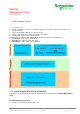
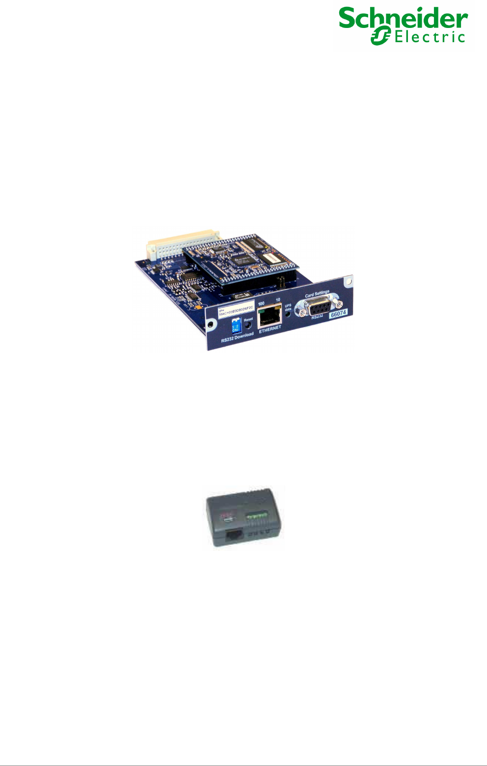
Network Management Card User Manual NMC Transverse - 66074 Environment Sensor - 66846 Network Management Card – User Manual 34003676EN/HA Page 1/81
Network Management Card User Manual Table of Contents 1 MGE NETWORK SOLUTION ____________________________________________________________5 1.1 INTRODUCTION _____________________________________________________________________5 1.1.1 Connecting the UPS / STS to the Network ___________________________________________5 The Network Management Card: __________________________________________________________5 1.1.2 Protecting the computers / servers _________________________________________________6 1.1.
Network Management Card User Manual 3.3.3 UPS Event log ________________________________________________________________30 3.3.4 STS Event log ________________________________________________________________30 3.3.5 System log ___________________________________________________________________32 3.4 NOTIFICATION _____________________________________________________________________34 3.4.1 UPS Email Notification__________________________________________________________34 3.4.
Network Management Card User Manual 8.1.1 UPS Alarm table ______________________________________________________________73 8.1.2 STS Alarm table_______________________________________________________________73 8.1.3 UPS event table _______________________________________________________________74 8.1.4 STS event table _______________________________________________________________76 8.1.5 System alarm table ____________________________________________________________78 8.
Network Management Card User Manual 1 MGE Network Solution 1.1 Introduction ◗ provides information on events concerning the supply of power to the computers connected to your computer network, ◗ carries out automatic shutdown of computer systems, ◗ monitors and controls all the UPSs connected to the network.
Network Management Card User Manual ◗ ◗ periodically accesses the information concerning the UPS / STS, makes this information available to the connected applications (Network Shutdown Modules, Web Browser, Network Management Systems, Enterprise Power Manager) Operation may be in standard secure mode (the default mode) or in SSL secure mode (Secure Socket Layer SSL). 1.1.
Network Management Card User Manual 1.1.4 Connection 1.1.4.1 How to connect UPS / network : ◗ ◗ Insert the optional card in the UPS / STS and connect the device to the computer network. Start the MGE UPS / STS, then the computers. 1.1.4.2 Setting up the protection, for UPS only ◗ ◗ Set up the Network Management Card (see user manual). Install Network Shutdown Module on all machines that are to be protected by the UPS (supplied with UPS battery backup power).
Network Management Card User Manual ◗ NMC Transverse for UPS, in UPS slot, like the MGE Galaxy PW, MGE Galaxy PW 1000, MGE Galaxy 3000, MGE Galaxy 4000 US, MGE Galaxy 5000, MGE Galaxy 5000 US ◗ NMC Transverse for UPS, using the Network Management Link, like the Comet 3000, Comet S31, MGE Galaxy 6000, MGE Galaxy 9000, EPS 6000 US, EPS 7000 US, EPS 8000 US ◗ NMC Transverse for STS, in STS slot, like the MGE Epsilon STS and MGE Upsilon STS .
Network Management Card User Manual 1.7 Technical data 1.7.1 Configuration The user can configure the card with one of the following means: ◗ Web browser ◗ Local serial link ◗ Telnet console ◗ BOOTP/DHCP ◗ Mupgrade 1.7.
Network Management Card User Manual ◗ Possibility of notification of status changes by e-mail, SMS or SNMP traps ◗ Position detection of 2 dry contacts (maximum sensor/contact distance: 20 m) ◗ Name and status of each configurable contact ◗ Recording of events and measurements in the card log ◗ Possibility of shutting down the installation in the event of a threshold being exceeded or on opening / closure of a dry contact ◗ Connection to the card with straight CAT5 RJ45 network cables (maximum card/sensor d
Network Management Card User Manual 2 Installation and Configuration For the following sections, read the installation manual supplied with the card or available for download on the www.apc.com web site in the “Download area” section . 2.1 Installation 2.1.1 Installing the card in the UPS / STS 2.1.2 Connecting the card to the IT network 2.1.3 Understanding front panel signals 2.2 Basic configuration 2.2.1 List of default parameters 2.2.2 Adjusting the network parameters 2.2.3 Rebooting the card 2.2.
Network Management Card User Manual 3 Supervision / Administration via a Web browser A JVM (Java Virtual Machine) is required to ensure correct display of information in HTML pages. ◗ ◗ 3.1 ◗ On a computer equipped with a Web browser (Internet Explorer or Netscape recommended), enter the address initialised previously in the Installation chapter (e.g.: http://213.30.17.30.) The “UPS properties” or “STS properties” home page is displayed.
Network Management Card User Manual 3.2 UPS / STS 3.2.1 “UPS properties” page ◗ This page gives instant access to the essential information about your UPS. This page is automatically refreshed every 10 seconds (by default). To change this value, go to the “System” page. 3.2.1.1 UPS zone: general information on the UPS.
Network Management Card User Manual • • • • • Battery operation • Load powered by main AC • Loss of communication with the UPS • Battery fault “Communication”: indicates the status of the communication between the card and the UPS “Power source”: indicates whether the power comes from the utility or from the UPS battery “Batteries”: indicates whether the battery is being charged or discharged “Output load level”: indicates the power percentage used at UPS output “Output”: indicates if the UPS output is p
Network Management Card User Manual 3.2.2 “STS properties” page ◗ This page gives instant access to the essential information about your STS. This page is automatically refreshed every 10 seconds (by default). To change this value, go to the “System” page. 3.2.2.1 STS zone: general information on the STS.
Network Management Card User Manual “Communication”: indicates the status of the communication between the card and the STS “Output”: indicates whether the output is or not powered “Output load level”: indicates the power percentage used at STS output “Transfer”: indicates if it is possible to switch from one used source to the other. 3.2.2.3 “Sources status” zone: ◗ “Active source”: indicate which source is currently used.
Network Management Card User Manual 3.2.4 On-line help On-line contextual help in English is available at the top of each page by clicking on the Help link, which is always located on the top right corner. The Help page always opens a new window. There is two help pages, dedicated to the device : one help for UPS, other one for STS.
Network Management Card User Manual Network Management Card – User Manual 34003676EN/HA Page 18/81
Network Management Card User Manual 3.2.5 UPS 3-Phase display Click 3-phase display to access to the detailed monitoring page This item is added to the menu for all single UPSs having a three-phase output. The link on the gauge symbols gives access to the measurement page related to the function. Function symbols are outlined in red when an alarm is present. The red triangle, linked to the alarm page, appears when an alarm is present, otherwise a green symbol is displayed.
Network Management Card User Manual 3.2.5.2 Battery measurements Remaining backup time estimted by the UPS Battery charge level Battery voltage Battery current – Negative when discharging Battery temp. – Internal temperature probe 3.2.5.
Network Management Card User Manual 3.2.6 STS 3-Phase display Click 3-phase display to access to the detailed monitoring page This item is added to the menu for all single UPSs having a three-phase output. The link on the gauge symbols gives access to the measurement page related to the function. Function symbols are outlined in red when an alarm is present. The red triangle, linked to the alarm page, appears when an alarm is present, otherwise a green symbol is displayed.
Network Management Card User Manual 3.2.6.1 Source 2 input measurement Source 1 current Source 1 voltage Phase / Phase Source 1 frequency Source 1 neutral current (if wiring 3 phases + neutral) 3.2.6.2 Source 2 input measurement Source 2 current Source 2 voltage Phase / Phase Source 2 frequency Source 2 neutral current (if wiring 3 phases + neutral) 3.2.7 UPS Control Click on the “UPS Control” section in the menu. If the UPS is not compatible with this function, a warning message is sent to the user.
Network Management Card User Manual ◗ ◗ The shutdown sequences take into account the time required for the registered servers to shut down without losing data (see shutdown parameters ). Once the sequence has started, the commands are disabled until it ends.
Network Management Card User Manual 3.2.8 UPS weekly schedule programming Click on the “Weekly schedule” section of the menu. If the UPS is not compatible with this function, a warning message is sent to the user. UPS configuration may also prevent the commands from being properly run. Read the UPS manual for more information. The weekly schedule enables the administrator to optimise power consumption or program a reboot of the protected equipment at a set time.
Network Management Card User Manual 3.2.9 Shutdown parameters ◗ Click on the “Shutdown parameters” section in the menu to see the list of parameters. Important note: For installations that do not use Network Shutdown Module (backup units, routers and other internetworking equipment, automated systems, etc.) or in the event of long backup periods, the card will send a command to the UPS (dependant of the UPS settings and UPS type) to shut off end of the programmed Shutdown After time.
Network Management Card User Manual 3.2.10 Viewing the alarms ◗ Click on the “Alarm table” section in the menu to view the list of current alarms. The table of managed alarms is included in the appendix.
Network Management Card User Manual 3.3 Logs 3.3.1 UPS Measurements Click on the “Measurements” section in the menu.
Network Management Card User Manual 3.3.2 STS Measurements Click on the “Measurements” section in the menu.
Network Management Card User Manual Select the time range to view Network Management Card – User Manual 34003676EN/HA Page 29/81
Network Management Card User Manual 3.3.3 UPS Event log Click in the “Event log” section of the menu. ◗ “Save Log” enables all values saved to be opened or saved in CSV format (compatible with Excel type spreadsheets). ◗ “Clear Log” enables deletion of all records. The administrator must enter his/her login / password to validate this action. Select the time range to view: See the table of events generated in the UPS event table. 3.3.4 STS Event log Click in the “Event log” section of the menu.
Network Management Card User Manual ◗ “Save Log” enables all values saved to be opened or saved in CSV format (compatible with Excel type spreadsheets). ◗ “Clear Log” enables deletion of all records. The administrator must enter his/her login / password to validate this action.
Network Management Card User Manual See the table of events generated in the STS event table. 3.3.5 System log Click in the “System log” section in the menu. ◗ “Save” enables all values saved to be opened or saved in CSV format (compatible with Excel type spreadsheets). ◗ “Clear” enables deletion of all records. The administrator must enter his/her login / password to validate this action.
Network Management Card User Manual Select the time range to view: See the table of events generated in the System Alarm Table.
Network Management Card User Manual 3.4 Notification 3.4.1 UPS Email Notification The card offers the possibility of redirecting UPS alarms to an e-mail server. The format of these e-mails is compatible with mobile telephone transfer systems using text messages (SMS). ◗ Notified events: The left side of the page shows the events that can be notified. By default, only the main events of battery operation and a few UPS alarms are accessible.
Network Management Card User Manual Environment alarms must be selected to activate e-mail notification of events concerning the Environment Sensor. The detail of notified events is accessed via the Configure Environment link. ◗ Recipient List: On the right side of this page, up to four recipients can be configured to receive e-mails from the card. Each addressee has its own trigger events, selected from the left side of the page, for which an e-mail is sent.
Network Management Card User Manual 3.4.2 STS Email Notification The card offers the possibility of redirecting STS alarms to an e-mail server. The format of these e-mails is compatible with mobile telephone transfer systems using text messages (SMS). ◗ Notified events: The left side of the page shows the events that can be notified. By default, only the events Output not powered and the STS general alarm are selected.
Network Management Card User Manual 3.4.3 Email Message Settings This page enables customisation of the content of the messages received by recipients of e-mails sent by the card. Customisation is common to the four recipients that can be notified (see E-mail notification). 3.4.3.1 UPS Email Message Settings ◗ Sender (32 characters maximum) identifies the source of the message. The default value is ups@domain.com. This field is free.
Network Management Card User Manual - Message text is a free zone. The body of the e-mail sent is composed of: - Message text, which is free text. - the date and time of the event, as saved in the log. - URL of the card, enabling a direct link with the card to be established. – Attachments, as configured for the e-mail recipients .- duplication of the subject, as configured. 3.4.3.
Network Management Card User Manual 3.4.
Network Management Card User Manual 3.5 Configuration The parameters of this menu can only be modified after entering the “User Name” and “Password”. The following screen is proposed automatically: User Name and password by default are: MGEUPS Each field accepts up to 10 characters max. After entering the login and password, these identifiers remain active as long as the browser is open, so you only have to enter them once. If the browser is closed, they will have to be re-entered.
Network Management Card User Manual 3.5.1 Network Settings Click on the “Network” section in the menu. This menu enables the administrator to configure the network parameters of the card and authorisation of the remote upgrade of the embedded system. ◗ ◗ ◗ IP address: The IP address of the card (e.g.: 123.49.134.36). Subnet Mask: The mask of the sub-network of your network (e.g.: 255.255.254.0).
Network Management Card User Manual ◗ Domain name is the domain to which the card belongs. This is the part of the full qualified domain name that follows the host name and is used by the DNS. The default value of the two parameters comprising the full qualified domain name: ups.domain.com ◗ TELNET connection: Authorises (choose enable) remote connection with a terminal to access the maintenance menu.
Network Management Card User Manual 3.5.2 System Click the “System” section in the menu. This menu enables the customisation of the information on the UPS properties / STS properties and Environment pages. ◗ UPS contact: This text field is limited to 32 characters. Enter the name of the person responsible for UPS administration at IT network level and/or electrical maintenance. This field does not appear on any other Web page. By default, its value is “Computer Room Manager”.
Network Management Card User Manual Choice of one of the available languages: English, French, Italian, German, Spanish changes the language of the html interface pages ◗ Note: Alarm notification remains in English / French (reboot the browser after modification). SNMP message remain in English. ◗ Environment log interval: [from 5 to 99999 sec ]. Temperature and humidity measurement save period. Default value = 300 sec. (only visible if the sensor is present).
Network Management Card User Manual 3.5.3 UPS Notified Applications Click the “Notified Application” section in the menu. Security: the administrator has to enter his login/password to view this information. This menu enables: ◗ The addition of the supervision stations receiving traps and configuration of the trap type. ◗ To list all the Notified Applications and the main parameters. ◗ Simulate events to test notification and shutdown of the Notified Applications.
Network Management Card User Manual ◗ Shutdown after : is the time available to the user from the Power failure until the launch of the shutoff sequence of the UPS. This parameter is optionnal. Many actions are available on this page : ◗ Remove : Depending on the kind of application, the selected ones will definitively disappear from the table as SNMP applications, or they will disappear and automatically re-subscribe as the Network Shutdown Module application.
Network Management Card User Manual ◗ Trap community indicates the name of the SNMP community For more details, read the MIB description document: available on the www.apc.com site. 3.5.4 Central Shutdown Configuration Click the “Notified Application” section in the menu then in “Configuration”.
Network Management Card User Manual This page is used to define either the shutdown or the notification settings used by the Network Shutdown Modules that connect to Network Management Card. These settings are used by the Network Shutdown Modules if they are in centralized-configuration mode or if their configuration is not valid. ◗ ◗ ◗ Shutdown After (time before shutdown) This is the time in seconds that the system waits following failure of AC power before initiating the system-shutdown procedure.
Network Management Card User Manual Select an entry in the list to modify the values in the edit zone at the bottom of the page. Note that the Network Shutdown Module must not be manually modified. The applications in the table appears in the order they have subscribed to the card. Following informations are displayed : ◗ ◗ ◗ Nr : is the index where the application is stored into the table.
Network Management Card User Manual ◗ Trap community indicates the name of the SNMP community For more details, read the MIB description document: available on the www.apc.com site. 3.5.6 Access control Click the “Access control” section in the menu. To access this page, the login and password are systematically requested if they have not already been entered. This menu enables configuration of the different parameters enabling secure access to the card via a browser or SNMP.
Network Management Card User Manual ◗ Enter New Manager Login: Text field limited to 10 characters. Enables secure access and modification of pages. Default value “MGEUPS”. ◗ Enter New Password: Text field limited to 10 characters. Enables secure access to the sections of the Configuration menu. Default value “MGEUPS”. ◗ Confirm New Password: Text field limited to 10 characters. Must be strictly identical (including upper/lower case) to the field above .
Network Management Card User Manual ◗ Change Community Read-only: Text field limited to 31 characters. This field is only validated after clicking on “Save” . Default value “public”. ◗ Current Community Read/Write is: Enables read and write SNMP access control (GET and SET). Default value “public”. ◗ Change Community Read/Write: Text field limited to 31 characters. This field is only validated after clicking on “Save” . Default value “public”.
Network Management Card User Manual 3.5.7 Time Click the “Time” section in the menu. This menu enables initialisation of the date and time of the card in three different ways. ◗ Synchronise manually: Enables initialisation of the date and time of the card, with the values entered in the Date and Time fields. Values are updated after clicking the “Save” button. ◗ Synchronise with computer time: Enables the date and time of your PC to be transferred to the card.
Network Management Card User Manual list. Connection is made with the server and the date and time are set after clicking on the “Save” button. Time is updated every hour. The card uses the NTP protocol (UDP 123 port) and the firewall must be set accordingly, no error message is generated if the time server contact fails ◗ Daylight Saving Time: Enables corrections due to summer / winter time changes, this option must be supported by the NTP server. Note 1: Time drift is related to card electronics.
Network Management Card User Manual ◗ Name and status of each contact can be configured ◗ Recording of events and measurements in the card log ◗ Possibility of shutting down the installation safely if one of the thresholds is exceeded or if a dry contact closes ◗ Connection to the Network Management Card by CAT5 straight RJ45 network cables (maximum card/sensor distance: 20m) 3.6.
Network Management Card User Manual The last status change of each contact is time-stamped. The Internet browser updates this page regularly according to the Environment refresh rate parameter on the System settings page.
Network Management Card User Manual 3.6.3 UPS Environment Settings 3.6.3.1 UPS Environment Settings The environment sensor measures temperature, humidity and gives the status of the 2 contacts (used for door, alarms or generator unit). The temperature and humidity thresholds can be adjusted and can trigger notification and correct shutdown of the protected system. The Sensor name is the function name given to the sensor, usually it enables location of the sensor.
Network Management Card User Manual The high alarm cannot be reactivated while temperature remains above the High threshold – Hysteresis value. The low alarm cannot be reactivated while temperature remains below Low threshold + hysteresis value. Humidity High threshold: if this value is exceeded, a notification is sent if enabled. Default value is 90%. Low threshold: if this value is exceeded, a notification is sent if enabled. Default value is 5%.
Network Management Card User Manual Same feature than for UPS, without the system shutdown only available for UPS. For detail see the UPS environment settings. 3.6.4 Log The environment sensor’s two measurements, Temperature and Humidity, are recorded at an interval defined by the Environment log interval parameter on the System settings page. By default, this period is 300 seconds. Each measurement is dated and stored in the log of the UPS’ communication card.
Network Management Card User Manual 4 Servers protection, UPS only 4.
Network Management Card User Manual 4.1.1.3 Shutdown when backup time is less than When the Network Management Card detects that the percentage of backup time remaining is less than the value set, the shutdown sequence is started. 4.1.1.4 Shutdown duration Duration required for the systems protected by the Shutdown Modules to shut down (in seconds). 4.1.
Network Management Card User Manual 4.2 The different server and UPS shutdown sequences 4.2.1 Extended power outage, shutdown initiated by the Shutdown Timer During battery backup time, the Shutdown Timer of the Network Management Card is reached: after a userdefined backup time period, the shutdown of all servers is initiated, followed by the UPS shutdown (depending on its configuration). The UPS restarts when utility power is restored (depending on its configuration).
Network Management Card User Manual 4.2.2 Extended power outage, shutdown initiated by the “Low battery power” message When the ”Low battery power” message is displayed, the UPS is shut off after taking into account the shutdown duration of the servers.
Network Management Card User Manual 4.2.3 Extended power outage, shutdown initiated by the Shutdown Timer, but utility restoration before the end of the Shutdown Duration If utility power is restored before the end of the Shutdown Duration, the UPS is shut off after the Shutdown Duration for a period equal to the forced reboot time delay Utility OFF Trap 17 Trap 11 Trap 29 ShutdownTimer Trap 18 Trap 31 ShutDurati on Trap 32 NSM 10s Reb oot Shutdow n UPS output Rebo ot OFF 4.2.
Network Management Card User Manual 5 Configuring a set of cards with Mupgrade This feature is particularly useful to configure large UPSs / STSs installed base. The Remote configuration features of Mupgrade allows you to import, modify and export configuration files from and to Network Management Cards. Configure all your Network Management Cards in four step : 1. Configure a Network Management Card located on the network through the html interface to create a master configuration.. 2.
Network Management Card User Manual 4. Reset Configuration To Default 5. Reset Agent 0. Exit Please Enter Your Choice => 6.1.1 Choice 1: SNMP agent configuration menu The blue lines are those displayed on screen.
Network Management Card User Manual Text field limited to 10 characters. Enables secure access to the sections of the Configuration menu. Default value “MGEUPS”. a. Manager Password :* Text field limited to 10 characters. Enables secure access to the sections of the Configuration menu. Default value “MGEUPS”. b. BOOTP/DHCP Enabled : Enabled Authorises the configuration of network parameters with your BootP/DHCP as a startup mode (choose enable).
Network Management Card User Manual [2] 0.0.0.0 [3] 0.0.0.0 [4] 0.0.0.0 public public public NotAccess NotAccess NotAccess COMMANDS 1. Modify - Modify an entry of table 2. Reset - Reset an entry to default from table 0. Return to previous menu Please Enter Your Choice => This menu enables configuration of access to the four supervision stations (identified by the IP address) with read/write community names different to those already defined in the card “1” menu.
Network Management Card User Manual 6.2 Configuration via Telnet You can access the configuration menu (see “configuration in local mode” section) from a station equipped with the Telnet protocol. As soon as the card is accessible on the network, enter the command: telnet < card IP address > to access the menu. The password defined by default is MGEUPS. The card will disconnect automatically after 3 minutes of inactivity. 6.
Network Management Card User Manual Execute PuTTY and select the following options:.
Network Management Card User Manual and Clic on « Open » to start connection Network Management Card – User Manual 34003676EN/HA Page 71/81
Network Management Card User Manual 7 Maintenance 7.1 Software upgrade 7.1.1 Card firmware upgrade using Mupgrade (Windows) This feature is particularly useful to upgrade a large UPS installed base in one operation. Read the relevant documentation available for download on the www.apc.com web site. 7.1.2 Card software upgrade via TFTP (UNIX and Windows) Upgrading is also possible with TFTP command. Generic command, with default value, is: tftp -i @IP put nmc_fb.
Network Management Card User Manual 8 Appendices 8.1 Tables of alarms and events 8.1.
Network Management Card User Manual Sources out of synchronization Emergency stop actived Output Thermal overload Output overload STS internal fault STS general alarm STS communication failure : Temperature is above high threshold xx °C ": Humidity is above high threshold xx %", : Temperature is below low threshold xx °C : Humidity is below low threshold xx % : :
Network Management Card User Manual UPS return to normal temperature %s on sequence started %s on sequence cancelled %s on sequence in progress %s on sequence completed %s off sequence started %s off sequence cancelled %s off sequence in progress %s off sequence completed %s toggle (off/on) sequence started %s toggle (off/on) sequence cancelled %s toggle (off/on) sequence in progress %s toggle (off/on) sequence completed UPS UPS communication failed UPS communication restored Unavailable battery Battery ava
Network Management Card User Manual : Humidity is in normal range : : : : : L'humidité est revenue à un niveau normal : : : :
Network Management Card User Manual normal range : Humidity is below low threshold %d % : Humidity is above high threshold %d % : Humidity is in normal range : : : : Network Management Card – User Manual un niveau normal : L'humidité est en dessous du seuil bas
Network Management Card User Manual 8.1.
Network Management Card User Manual 8.2 Glossary Bootp: Protocol based on UDP used to allocate an IP address corresponding to an Ethernet card during the startup phase. Defined by the RCF 951 Community name: Access key to access SNMP agent information DHCP Dynamic Host Configuration Protocol This IETF protocol enables remote, automatic, self-configuration of the IP addresses of a workstation.
Network Management Card User Manual NETWORK MANAGEMENT CARD Communication cards to supervise UPS and communicate with Network Shutdown Module to insure power protection on servers NMS NETWORK MANAGEMENT STATION (SNMP) The dedicated PC or workstation is used on the company’s networks to administrate all devices connected to the network. Data are transmitted using the SNMP protocol. Popular NMS systems include HP OpenView, IBM Tivoli, CA Unicenter, etc.
Network Management Card User Manual Trap (SNMP) This term describes an event that affects an MIB variable. Traps are sent to the manager, which is programmed to perform specific tasks upon reception of the traps.