DC Power Plant Product Manual MX28B600 December 2002 Part# 990-0564 Downloaded from Arrow.com. APC DCNS Inc.
REVISION HISTORY Revision Downloaded from Arrow.com. Date By Description 07/10/01 JNF Initial release.
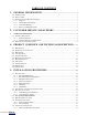
TABLE OF CONTENTS 1. GENERAL INFORMATION ................................................................................................1 1.1 INTRODUCTION .............................................................................................................................................1 1.2 PRECAUTIONS................................................................................................................................................1 1.3 INSPECTION UPON RECEIPT OF GOODS ...............
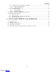
MX28B600 5.7.2 Installation of Circuit Breakers and Fuses ................................................................................18 5.7.2.1 Plug-in Circuit Breakers .................................................................................................................. 18 5.7.2.2 Optional GMT Fuses ........................................................................................................................ 18 5.7.3 Load Connections .............................................
MX28B600 1. GENERAL INFORMATION 1.1 Introduction DC Power Plants from APC DC Network Solutions Inc. (hereafter in this document “APC”) have unique features that make them easy to install, maintain, and upgrade. The rectifier units are modular and truly “hot-pluggable” into the shelf assembly without any separate AC wiring.
MX28B600 1) Make a descriptive notation on the delivery receipt before signing. 2) File a damage or shortage report with the carrier that delivered the shipment. 1.3.3 Concealed Damage It is the customer’s responsibility to unpack the power system and equipment received from APC and check for concealed damage, within 15 days of receipt of any and all materials.
MX28B600 2. CUSTOMER SERVICE AND SUPPORT APC manufactures standby power plants and systems, and provides customers with complete product and systems support and service. APC has an international network of factory trained service technicians. The service organization is on call 24 hours a day, 365 days a year. If there is a problem with the power system, contact APC DCNS at 1-800-800-4APC When you contact APC you should refer to your supplier as DC Network Solutions.
MX28B600 3. WARRANTY PROVISIONS 3.1 General Provisions APC DC Network Solutions Inc. warrants the power equipment and components it manufactures or sells against defective materials and workmanship for a period of TWO (2) YEARS from the date of shipment. 3.1.
MX28B600 5. APC shall not be liable to the user (purchaser), or any third party, for indirect, incidental, or consequential damages such as, but not limited to, loss of use, loss of profits, costs associated with removal/installation of a defective product(s) or component(s) arising out of the sale or relating to the use of this product; and the user (purchaser) assumes all responsibility for all personal injury and property damage resulting from the handling, possession, or use of the product.
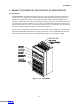
MX28B600 4. PRODUCT OVERVIEW AND TECHNICAL DESCRIPTION 4.1 Description The MX28B600 is a modular stand-alone -48V DC power plant with a microprocessor-based control unit. It is configurable in such a manner that it will support most typical applications within the specified current range of 600 amperes without special application engineering or assistance.
MX28B600-48V Downloaded from Arrow.com.
MX28B600-48V 4.2 Power Output Capacity 600 amps maximum, or 550 amps with N+1 redundancy. The housing provides space for three rectifier shelves that can hold up to four rectifiers each, a control unit, and two tiers of up to 43 distribution circuit breakers. 4.3 Rectifiers The rectifiers are APC DC Network Solutions, Inc. Model MRF28H54BV with specifications as follows: • Input Voltage: 176-264V AC (230V AC nominal) @ 45-66 Hz • Input Current per Rectifier: 13.
MX28B600-48V 4.5 AC Input Power Each rectifier requires 208/220/240V AC, single-phase, 50/60 Hz, supplied through an external 20-amp two-pole breaker. There are three entry points (one for each rectifier shelf), for customer-supplied one-inch conduit. Section 5.2 for details on electrical connection. 4.6 Battery connections Battery connections are made by feeding the cables thru the bottom-rear of the unit. Use caution when running the cables to not damage other components. (Figure 4.6-1).
MX28B600-48V 4.7 DC Distribution Two plug-in circuit breaker tiers, consisting of a 24-position panel and two 10-position panels, provide 43 positions of -48V distribution. One position is reserved for the Manual Battery Disconnect Switch. The breaker tiers are center fed via bus bars to the -48V DC bus with each side having an ampacity of 300A. Connections for -48V DC loads, requiring standard #10-32 two-hole lugs on 5/8-inch centers, are located directly above the corresponding breaker.
MX28B600-48V 4.10 Mechanical • Dimensions: 42" high x 23" wide x 20"deep (1066x584x508mm) • Weight: Housing - 190 lbs. (86kg) Rectifier - 11 lbs each. (5kg) • Color: Dawn Gray (fronts) NOTE: Descriptions & sizes are for the power system alone; when installed with inverters, batteries, etc., dimensions & weight will be affected. 4.11 Compliance • UL 1950 • NEBS – level 3 • FCC Part 15, Class A 11 Downloaded from Arrow.com.
MX28B600-48V 5. INSTALLATION PROCEDURES 5.1 Preparation 5.1.1 Recommended Tools • Standard selection of insulated hand tools. • Proper tools for crimping the selected cable lugs. 5.1.2 Recommended Test Equipment • Digital Multimeter 5.1.3 Equipment Inspection Remove equipment from packing material and inspect for shipping damage to verify the safety and operational suitability for the installation site. [Refer to Section 1.3] 5.1.
MX28B600-48V Prior to installation, drawings, floor loading requirements, external alarm points, AC service entrance, and grounding schemes should all be checked and confirmed. If batteries are to be mounted in a room separate from the power plant, careful attention should be paid to battery cable voltage drop effects.
MX28B600-48V 5.3.1 Cable Sizing Considerations The battery cable(s) should be sized sufficiently large to limit the voltage drop from the MX28B600 DC power plant to the battery during charging in accordance with system design requirements. The cable(s) must also carry the full load current during battery operation. If assistance is required to determine the necessary cables for the application, contact your sales representative or APC DC Network Solutions Inc. 5.3.
MX28B600-48V Figure 5.6 Interface Board 5.6.1 External Alarm Inputs Four external alarm inputs with assignable priority levels are available. These alarm inputs respond to external dry contact closures between normally open (NO) and common (C) or contact openings between normally closed (NC) and C (see Table 5.6-1). External Alarm Source (non-alarm state) Connect To Input Alarm Terminals OPEN CLOSED NO-C NC-C Table 5.6-1. External Alarm Input Definition Table 5.
MX28B600-48V 5.6.2 Alarm Outputs There are eight alarms available that provide outputs via Form “C” relay contacts. The last two of these are pre-assigned as the Minor and Major alarm outputs. The Major relay is energized (NO-C contacts closed) during normal (non-alarm) operating conditions; all the other relays energize when an alarm condition occurs. The other six outputs are initially designated as “Relay 1” through “Relay 6” (the user may assign more meaningful names if desired).
MX28B600-48V * BREAKER RATING PART NUMBER BREAKER RATING PART NUMBER 1A FFA-0014 40 A FFA-0020 3A FFA-0015 50 A FFA-0025 5A FFA-0016 60 A FFA-0021-X * 10 A FFA-0017 70 A FFA-0022-X * 15 A FFA-0028 80 A FFA-0023-X * 20 A FFA-0018 100 A FFA-0024-X * 30 A FFA-0019 -1: adapter has #10 studs on 5/8” centers for two-hole cable lug -2: adapter has #10 studs on ¾” centers for two-hole cable lug -3: adapter has ¼” studs on 1” centers for two-hole cable lug Table 5.7-1.
MX28B600-48V 5.7.2 Installation of Circuit Breakers and Fuses 5.7.2.1 Plug-in Circuit Breakers 1) Remove the circuit breaker cover panel and the plastic cover(s)/insert(s) from the desired location(s). 2) Install the circuit breaker(s) by snapping the top terminal onto the upper bus bar and rotating the unit down until the second terminal snaps onto the breaker termination post as shown in Figure 5.7-1.
MX28B600-48V a 50 A. circuit breaker located in circuit breaker Position 1. The interface card provides fuseholders for eight fuses, labeled “F1” through “F8”, which can be used for small -48V DC loads. The maximum fuse size that should be used is 10A. 5.7.3 Load Connections 5.7.3.1 Circuit Breakers Connections for -48V DC loads require standard two-hole lugs for #10 screws on 5/8” centers and are located directly above the corresponding circuit breaker.
MX28B600-48V 5.9.1 Apply AC Power Turn on the circuit breakers that supply AC power to the rectifiers in the MX28B600 DC power plant. The main screen should appear on the control unit display (see Figure 5.9-1). The display on the control unit is a 2-lines by 16-characters display. The cursor cycles below the characters of the active selection on the display. Information shown in the second line of Figure 5.
MX28B600-48V 3) Turn on all the circuit breakers that supply AC power to the rectifiers in the MX28B600 DC power plant. 4) Load circuit breakers may now be turned on as required. 21 Downloaded from Arrow.com.
MX28B600-48V 6. SETUP, ADJUSTMENTS, AND OPERATION 6.1 User Interface The MX28B600 control unit provides a user interface designed with a hierarchical menu that can be viewed on the 32-character display by “navigating” with the “Õ” (left), “Ö” (right), “×” (up), and “Ø” (down) arrow keys located on the front panel. The selected item on the display is identified by the cursor cycling beneath its characters.
MX28B600-48V 6.3 External Alarm Inputs The four external alarm inputs (also referred to as “Input Relay Alarms”) can be assigned a priority and routed or “mapped” to alarm output relays. Available assignments are “Ignore”, “Major”, “Minor”, and “Relay 1” ∙∙∙ “Relay 6”. Screens for making the assignments are located at [SYSTEM/IN-RLY/RLY-MAP]. A user defined name or “alias” may also be assigned to each of these input alarms. Screens for making these assignments are located at [SYSTEM/IN-RLY/ALIAS].
MX28B600-48V Table 6.5-1. Parameter Locations, Descriptions, and Default Values PARAMETER DESCRIPTION DISPLAY SCREENS / DEFAULT SETTINGS SYSTEM SETUP Password Entry Screen for entry of the active password (PIN). PIN m+ 0000 Level 1 PIN {2} [SYSTEM/SETUP] Password (PIN) that permits security Level 1 parameter changes - limited access. PIN 1 m+ 1111 Level 2 Password {2} [SYSTEM/SETUP] Password (PIN) that permits security Level 2 parameter changes - unlimited access.
MX28B600-48V (Table 6.5-1. Parameter Locations, Descriptions, and Default Values) PARAMETER DESCRIPTION DISPLAY SCREENS / DEFAULT SETTINGS Type number for the control unit display. Display Type + 000255 Date {1} [SYSTEM/DATE] Internal system calendar date. Date m+ JUN 27 2001 Time {1} [SYSTEM/DATE] Internal system clock time (24-hour format). Time High Voltage Threshold {1} [SYSTEM/SET-ALM] System High voltage alarm threshold. Sys HV Thr m+ -58.
MX28B600-48V (Table 6.5-1. Parameter Locations, Descriptions, and Default Values) PARAMETER Test Relay 1 {1} [SYSTEM/DIAG] • • • DESCRIPTION Setting this parameter to “ON” energizes Relay 1 and turns on the “ALM1” LED on the control unit front panel. DISPLAY SCREENS / DEFAULT SETTINGS Test Relay 1 m+ OFF • • • • • • Test Relay 6 {1} [SYSTEM/DIAG] Setting this parameter to “ON” energizes Relay 6 and turns on the “ALM6” LED on the control unit front panel.
MX28B600-48V (Table 6.5-1. Parameter Locations, Descriptions, and Default Values) PARAMETER DESCRIPTION DISPLAY SCREENS / DEFAULT SETTINGS Battery Alarms Discharge Alarm {1} [BATT/SET-ALM] An alarm that is generated if the battery discharge current exceeds the programmed battery discharge threshold. Batt Disc Alm m+ Minor High Voltage Alarm {1} [BATT/SET-ALM] An alarm that is generated if the magnitude of the battery voltage rises above the high voltage threshold.
MX28B600-48V (Table 6.5-1. Parameter Locations, Descriptions, and Default Values) PARAMETER DESCRIPTION DISPLAY SCREENS / DEFAULT SETTINGS Standby Alarm {1} [MODULES/RECT/SET-ALM] This alarm indicates that the control unit is holding a rectifier in the standby mode. Rect Stdby Almm+ n of N Fan Fail Alarm {1} [MODULES/RECT/SET-ALM] This alarm indicates that a rectifier fan has failed.
MX28B600-48V (Table 6.5-1. Parameter Locations, Descriptions, and Default Values) PARAMETER DESCRIPTION DISPLAY SCREENS / DEFAULT SETTINGS FUSE Fuse Alarms Fuse 1 Blown {1} [MODULES/FUSE/SET-ALM] • • • Fuse 16 Blown {1} [MODULES/FUSE/SET-ALM] An alarm that indicates Fuse 1 is blown. • • • FUSE 1 Alm m+ Major • • • An alarm that indicates Fuse 16 is blown. FUSE 16 Alm m+ Major An alternate name (alias) can be assigned to the relay if desired.
MX28B600-48V (Table 6.5-1. Parameter Locations, Descriptions, and Default Values) PARAMETER DESCRIPTION DISPLAY SCREENS / DEFAULT SETTINGS Output Relay Major Alias {1} [SYSTEM/OUT-RLY/ALIAS] An alternate name (alias) can be assigned to the relay if desired. Relay Major m+ Major Output Relay 1 Delay {1} [SYSTEM/OUT-RLY/RLY-MAP] Delay between sensing of the alarm condition and activation of the alarm relay. An alarm condition must exist for longer than the delay to be activated.
MX28B600-48V 31 Downloaded from Arrow.com.
MX28B600-48V Figure 6.4-1.
MX28B600-48V (Figure 6.4-1.
MX28B600-48V (Figure 6.4-1.
MX28B600-48V Cir Bkr 7 Cir Bkr 8 • • • Cir Bkr 70 Cir Bkr 71 Cir Bkr 72 FUSE SET-ALM FUSE FUSE FUSE FUSE FUSE FUSE FUSE FUSE FUSE FUSE FUSE FUSE FUSE FUSE FUSE FUSE ALIAS FUSE FUSE FUSE FUSE FUSE FUSE FUSE FUSE FUSE FUSE FUSE FUSE FUSE FUSE FUSE FUSE 1 Alm 2 Alm 3 Alm 4 Alm 5 Alm 6 Alm 7 Alm 8 Alm 9 Alm 10 Alm 11 Alm 12 Alm 13 Alm 14 Alm 15 Alm 16 Alm 1 2 3 4 5 6 7 8 9 10 11 12 13 14 15 16 35 Downloaded from Arrow.com.
MX28B600-48V (Figure 6.4-1. Control Unit Menu Structure) LVD SET-ALM LVD1 LVD1 LVD2 LVD2 PARAM LVD1 LVD1 LVD2 LVD2 Option Open Alm Option Open Alm Trip Reset Trip Reset BATT SET-ALM Batt Disc Thr Batt Disc Alm Batt HV Thr Batt HV Alm Batt LV Thr Batt LV Alm Batt HT Thr Batt HT Alm Batt LT Thr Batt LT Alm PARAM Batt Float Batt Max Rech COMP Comp Method Comp TC Comp HKnee Comp LKnee PIN PIN OEM OEM R Offset OEM R Gain OEM S Offset OEM S Gain 36 Downloaded from Arrow.com.