Installation and Quick Configuration Manual NetBotz® Room Monitor 455 NBWL0455 NBWL0456
This manual is available in English on the enclosed CD. Dieses Handbuch ist in Deutsch auf der beiliegenden CD-ROM verfügbar. Este manual está disponible en español en el CD-ROM adjunto. Ce manuel est disponible en français sur le CD-ROM ci-inclus. Questo manuale è disponibile in italiano nel CD-ROM allegato. 本マニュアルの日本語版は同梱の CD-ROM からご覧になれます。 Instrukcja obsługi w języku polskim jest dostępna na CD. O manual em Português está disponível no CD-ROM em anexo.
Contents Introduction 1 Product Description . . . . . . . . . . . . . . . . . . . . . . . . . . . . . . . . . . . . 1 Document Overview . . . . . . . . . . . . . . . . . . . . . . . . . . . . . . . . . . . . 2 Related Documents . . . . . . . . . . . . . . . . . . . . . . . . . . . . . . . . . . . . 2 Additional Options . . . . . . . . . . . . . . . . . . . . . . . . . . . . . . . . . . . . . 3 InfraStruXure-certified . . . . . . . . . . . . . . . . . . . . . . . . . . . . . . . . . .
The APC Configuration Wizard . . . . . . . . . . . . . . . . . . . . . . . . . . 19 Access an Appliance . . . . . . . . . . . . . . . . . . . . . . . . . . . . . . . . . . 20 Overview . . . . . . . . . . . . . . . . . . . . . . . . . . . . . . . . . . . . 20 Administrator account user ID and password . . . . . . . . . 20 Root account user ID and password . . . . . . . . . . . . . . . 20 Lost password recovery . . . . . . . . . . . . . . . . . . . . . . . . . 21 Basic View . . . . . . . . . . . . . . . . . .
Introduction Product Description The American Power Conversion (APC®) NetBotz® Room Monitor 455 functions as the central hardware appliance for a NetBotz security and environmental monitoring system. The NetBotz 455 can be installed anywhere in a room and includes an integrated camera and internal sensors that monitor temperature, humidity, air flow, and motion.
Attention: THE EQUIPMENT CONTAINS, AND THE SOFTWARE ENABLES, VISUAL RECORDING CAPABILITIES, THE IMPROPER USE OF WHICH MAY SUBJECT YOU TO CIVIL AND CRIMINAL PENALTIES. APPLICABLE LAWS REGARDING THE USE OF SUCH CAPABILITIES VARY BETWEEN JURISDICTIONS AND MAY REQUIRE AMONG OTHER THINGS EXPRESS WRITTEN CONSENT FROM RECORDED SUBJECTS. YOU ARE SOLELY RESPONSIBLE FOR INSURING STRICT COMPLIANCE WITH SUCH LAWS AND FOR STRICT ADHERENCE TO ANY/ALL RIGHTS OF PRIVACY AND PERSONALTY.
Additional Options The following options are available for the NetBotz 455. For more information about any of the options, contact your APC representative or the distributor from whom you purchased your APC product.
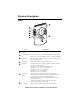
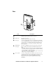
Physical Description Front Item 4 Description Vented internal sensors Network link LED Shows the status of the network connection. Blinks to indicate network traffic (green—connected at 10 Mbps; yellow—connected at 100 Mbps). Power LED Indicates whether the unit is receiving power (green—receiving power; dark—not receiving power). Camera LED Blinks steadily when the integrated camera is active. Alert LED Indicates the alert status of the system.
Rear Item Description Microphone jack Supports audio sensing, audio recording, and two-way audio. Maximum length of microphone cable: 3 m (9.8 ft). Speaker jack Supports two-way audio. Maximum length of speaker cable: 3 m (9.8 ft). A-Link port Used for cascading NetBotz sensor pods and temperature and humidity sensors with digital displays. Provides communications and power to the connected devices over standard CAT-5 cabling with straight-through wiring.
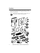
Inventory Inspect the contents of the package to ensure that the parts included match those shown below. Report missing or damaged contents to APC or your APC reseller. However, if damage was due to shipping, immediately report the damage to the shipping agent. The shipping and packaging materials are recyclable. Please save them for later use or dispose of them appropriately.
Item Description NetBotz Room Monitor 455 Bracket mounting plate for electrical boxes Extender arms Ball-joint adjuster arms T-bar mounting plate Rubber bracket cover Mounting plate Cable retainer Mounting screw wall anchors Extender arm set screw 203-mm (8-in) tie wraps Adhesive cable tie holders 13-mm (0.5-in) machine screws (for electrical box) 19-mm (0.75-in) sheet metal screws (for wall or enclosure) 1.
Installation Install the NetBotz 455 Choose an installation option that meets your needs. Take the following into consideration: Caution: Only connect approved devices to ports on the NetBotz 455 as directed in this manual. Plugging in other devices may result in equipment damage. Note: Consider the location of the nearest network port. Note: Make sure the camera will not be obstructed. Note: Consider cable routing for all sensors that you plan to connect to the appliance.
Wall Note: Drill 4.76-mm (3/16-in) pilot holes for wall anchors. Caution: Do not overtighten the screws.
Ceiling 10 NetBotz 455 Installation and Quick Configuration Manual
Enclosure Note: Use a #32 drill to make four 2.94-mm (0.116-in) pilot holes.
Connect the NetBotz 455 to Your Network Power-over-Ethernet (PoE) injector Caution: Before you energize the NetBotz 455, review the electrical specifications on page 31 to avoid overloading the circuit. Caution: Be sure the appliance is properly grounded by plugging the power cord directly into a wall outlet or by verifying the ground path if you are using a power strip.
Connect Sensors to Sensor Ports This procedure applies to the following sensors, which are supported by the NetBotz 455 and connect to the sensor ports: • Temperature Sensor (AP9335T) • Temperature/Humidity Sensor (AP9335TH) • NetBotz Vibration Sensor (NBES0306) • NetBotz Smoke Sensor (NBES0307) • NetBotz Spot Fluid Sensor (NBES0301) • NetBotz 0-5 V Sensor Cable (NBES0305) • NetBotz Door Switch Sensor for APC Racks (NBES0303) • NetBotz Door Switch Sensor for Rooms or Third Party Racks (NBES0302) • NetBotz D
Connect Sensors and Sensor Pods to A-Link Ports You can cascade up to a combined total of two NetBotz Rack Sensor Pod 150s (NBPD0150) and NetBotz Room Sensor Pod 155s (NBPD0155) and up to a combined total of eight Temperature Sensors with Digital Display (AP9520T) and Temperature/Humidity Sensors with Digital Display (AP9520TH). You cannot cascade appliances. Use one appliance per system. A-Link is an APC proprietary CAN (Controller Area Network) bus.
Adjust the Lens View the camera feed during the adjustment of the camera in order to correctly adjust the focus of the feed and field of view settings. lens housing To access the adjustment screws, remove the lens housing by turning the lens housing counter-clockwise until the latches disengage. unlock lock aperture To reattach the lens housing, engage the latches and rotate the housing clockwise until a click is heard.
Initial Configuration Note: Disregard the procedures in this section if you have APC InfraStruXure Central as part of your system. See the documentation for your InfraStruXure device for more information.
• Microsoft® Windows® Systems: To install the applications and the JRE on a computer running Windows XP SP1 or SP2, or Windows 2000, place the NetBotz Appliance Utility CD in the CD drive of the computer that you will use to configure and manage your appliance. The NetBotz Installer starts automatically. If you have disabled Autorun on your computer, click Start > Run, type x:\av\windows\install.exe in the Open field (where x is the drive letter assigned to your CD drive) and click OK.
Note: If the COM port associated with the port to which your USB cable is connected is currently in use by another application, the message beside the COM port in the Owner column indicates that the port is not available. To correct this, close the application that is using the COM port and click Scan Serial Ports. 5. The Root Password window appears. Enter the administrator account password for this appliance (apc, by default) and click OK. 6.
Install a wireless network device You can install a third-party wireless network device by connecting it to the Ethernet port on the appliance using an Ethernet cable. APC currently supports the D-Link DWL-G820, a wireless Ethernet bridge. To install and configure a third-party wireless network device, see the instructions provided with that device.
Access an Appliance Overview After the appliance is running on your network, you can access the configured appliance through the Basic View or the Advanced View. Administrator account user ID and password Your NetBotz appliance has a pre-configured Administrator account. The User ID and Password for this account are: • User ID: apc • Password: apc Note: To increase security, be sure to use the Advanced View Users task to change the default User ID and Password for the Administrator account.
Lost password recovery To recover from a lost password: 1. Locate the reset switch on the bottom of the appliance. 2. Use a thin wire such as a paper clip to press the reset switch for 10 seconds. This causes the system to restart. 3.
Advanced View Use the Advanced View to view sensor data, camera images, and other appliance data in a custom Java application. You can also use the Advanced View to generate relay output actions and configure all appliance features. The Advanced View is a stand-alone application that must be installed on a supported network-attached computer. For more information on the Basic View or the Advanced View, see the NetBotz Appliance User’s Guide.
Configure appliance settings Open the Advanced View and perform the following Appliance Settings tasks. The icons associated with each task are located in the Configuration pane, in the Appliance Settings region. 1. Set the Clock settings. By default, your appliance synchronizes the system clock with the default NTP servers. If network access to these servers is not permitted, double-click on the Clock icon and specify your NTP server address or manually specify clock settings. 2. Set DNS settings.
Configure alert actions You can configure your appliance to play audio alert notifications through the headphone/speaker jack on your Camera Pod 160 or Camera Pod 120 or to send an e-mail alert notification to your e-mail address when sensor thresholds are violated. Open the Advanced View and perform the following Pod/Alerts Settings tasks. The icons associated with each task are located in the Configuration pane, in the Pod/Alerts Settings region. 1. Open the Alert Actions task.
Upgrade Options Software Feature Upgrades The BotzWare on your appliance can be upgraded using the Upgrade task in the Advanced View. The following software packs can be added to your appliance.
Add pods to your appliance The NetBotz Room Monitor 455 supports the following pods: • A combined total of two Camera Pod 160s, Camera Pod 160s, and CCTV Adapter Pod 120s. • A combined total of two Sensor Pod 150s, Sensor Pod 155s, Sensor Pod 120s, and 4-20mA Input Pod 120s. Camera Pods, Sensor Pod 120s, and 4-20mA Input Pod 120s can be connected directly to the appliance USB port, or you can connect a USB hub to your appliance and then connect pods to the hub.
Install and configure a CCTV adapter pod 120. To install a CCTV Adapter Pod 120, connect your video source to the appropriate DIN, BNC, or RCA video input jack on the pod. Use the USB cable to connect your pod to your NetBotz appliance, or to a USB hub connected to the appliance.
Connect a USB modem You can enhance the network communication capabilities of your appliance by connecting a supported USB modem to your appliance. The following USB modems are supported for use with the appliance: • MultiTech® MultiModem® GPRS • MultiTech MultiMobile™ USB • Option GlobeSurfer® iCon Connect the USB modem to your appliance, or to a USB hub that is connected to the appliance.
Connect an APC Switched Rack PDU To connect an APC Switched Rack PDU 79xx to your appliance, connect a USB-to-serial cable (NBAC0226, available from APC and APC resellers) to the RJ-12-to-DB9 serial cable (940-0144A) included with the Rack PDU. Connect your USB-to-serial cable to your appliance, or to a USB hub that is connected to the appliance. Once you connect the USB-to-serial cable to your appliance, you can connect the Rack PDU to the RJ-12-to-DB9 serial cable for use with your appliance.
Connect external sensors To install an external sensor, plug the sensor into an available External Port on any Sensor Pod 150, Sensor Pod 155, or Sensor Pod 120. Note: When connecting a sensor to a Sensor Pod 120, be sure to note both the sensor pod serial number, located on the back of the pod, and the number of the External Port on the pod when you connect the cable. You will need this information when you use the sensor pod task to configure your appliance.
Specifications Electrical Input voltage, nominal 48 VDC (Power-over-Ethernet) Maximum power consumption 15 W Physical Dimensions (H x W x D) 210 x 170 x 94 mm (8.3 x 6.7 x 3.7 in) Weight 0.64 kg (1.
Warranty Two-Year Factory Warranty This warranty applies only to the products you purchase for your use in accordance with this manual. Terms of warranty APC warrants its products to be free from defects in materials and workmanship for a period of two years from the date of purchase. APC will repair or replace defective products covered by this warranty. This warranty does not apply to equipment that has been damaged by accident, negligence or misapplication or has been altered or modified in any way.
OR SERVICE IN CONNECTION WITH THE PRODUCTS. THE FOREGOING WARRANTIES AND REMEDIES ARE EXCLUSIVE AND IN LIEU OF ALL OTHER WARRANTIES AND REMEDIES. THE WARRANTIES SET FORTH ABOVE CONSTITUTE APC’S SOLE LIABILITY AND PURCHASER’S EXCLUSIVE REMEDY FOR ANY BREACH OF SUCH WARRANTIES. APC WARRANTIES EXTEND ONLY TO PURCHASER AND ARE NOT EXTENDED TO ANY THIRD PARTIES.
Radio Frequency Interference Changes or modifications to this unit not expressly approved by the party responsible for compliance could void the user’s authority to operate this equipment. USA —FCC This equipment has been tested and found to comply with the limits for a Class A digital device, pursuant to part 15 of the FCC Rules. These limits are designed to provide reasonable protection against harmful interference when the equipment is operated in a commercial environment.
Australia and New Zealand Attention: This is a Class A product. In a domestic environment this product may cause radio interference in which case the user may be required to take adequate measures. European Union This product is in conformity with the protection requirements of EU Council Directive 2004/108/EC on the approximation of the laws of the Member States relating to electromagnetic compatibility.
APC Worldwide Customer Support Customer support for this or any other APC product is available at no charge in any of the following ways: • Visit the APC Web site to access documents in the APC Knowledge Base and to submit customer support requests. – www.apc.com (Corporate Headquarters) Connect to localized APC Web sites for specific countries, each of which provides customer support information. – www.apc.com/support/ Global support searching APC Knowledge Base and using e-support.