Unpacking, Installation, and Customization NetShelter® SX Networking Enclosure U.S. Patent No.
This manual is available in English on the enclosed CD. Dieses Handbuch ist in Deutsch auf der beiliegenden CD-ROM verfügbar. Este manual está disponible en español en el CD-ROM adjunto. Ce manuel est disponible en français sur le CD-ROM ci-inclus. Questo manuale è disponibile in italiano nel CD-ROM allegato. 本マニュアルの日本語版は同梱の CD-ROM からご覧になれます。 Instrukcja obs³ugi w jêzyku polskim jest dostêpna na CD. O manual em Português está disponível no CD-ROM em anexo.
Contents Product Overview ........................................................... 1 Description . . . . . . . . . . . . . . . . . . . . . . . . . . . . . . . . . . . . . . . . . . . . . 1 NetShelter SX Networking Enclosures . . . . . . . . . . . . . . . . . . . . . . . 1 Product Inventory . . . . . . . . . . . . . . . . . . . . . . . . . . . . . . . . . . . . . . . . 2 Components of the enclosure . . . . . . . . . . . . . . . . . . . . . . . . . . . . . . 2 Before Installation ........................
Removing and Installing the Doors . . . . . . . . . . . . . . . . . . . . . . . . . 12 Removing the doors . . . . . . . . . . . . . . . . . . . . . . . . . . . . . . . . . . . . . 12 Installing the doors . . . . . . . . . . . . . . . . . . . . . . . . . . . . . . . . . . . . . . 12 Reversing the front door . . . . . . . . . . . . . . . . . . . . . . . . . . . . . . . . . . 13 Vertical Mounting Flanges . . . . . . . . . . . . . . . . . . . . . . . . . . . . . . . .
Product Overview Description The APC by Schneider Electric NetShelter® SX Networking 750-mm wide enclosure is a high-quality enclosure for storage of industry-standard (EIA-310), 19-inch rack-mount hardware, which includes servers, and voice, data, networking, internetworking, and APC power protection equipment. NetShelter SX Networking Enclosures †One Model Rack Mounting Height Rack Mounting Width External Enclosure Width Enclosure Depth AR3140 42 U† 482 mm (19 in) 750 mm (29.
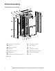
Product Inventory Components of the enclosure Vertical 0U Accessory Channel Reversible curved door Split doors APC nameplate Side panels with locks Key Frame posts Vertical cable managers Adjustable leveling feet Mounting flange cable manager Hardware bag Vertical mounting flanges Airflow management panels accessory bag Roof Casters 2 NetShelter SX Networking Enclosure—Unpacking, Installation, and Customization
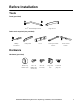
Before Installation Tools Tools (provided) Torx® T30/#2 Phillips wrench Cage nut tool Other tools required (not provided) Phillips screwdriver Utility knife Level 13-mm open-ended wrench 10-mm socket wrench Hardware Hardware (provided) Plastic cup washers (60) M6 x 16 Phillips slot screws (60) M5 x 12 screws (4) Cage nuts (60) 7-mm hole plugs (4) NetShelter SX Networking Enclosure—Unpacking, Installation, and Customization 3
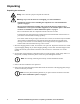
Unpacking Unpacking the enclosure Heavy: Use at least two people to unpack the enclosure. Warning: To prevent the enclosure from tipping over after installation: • Stabilize the enclosure before installing the components. See “Rack stabilization options” on page 8. • Do not extend components on sliding rails out from the enclosure until you have installed three or more pieces of similar equipment, or the stabilizer plate or bolt-down brackets are installed. See “Rack stabilization options” on page 8.
5. With one person on each side of the enclosure, carefully roll it toward the rear of the pallet until the rear casters clear the back edge of the pallet. Continue to slide the enclosure rearward until the rear casters touch the floor. 6. While one person carefully tips the enclosure slightly away from the pallet, have the other person pull the pallet away from the enclosure. Set the enclosure gently on its casters. Note: Save the pallet if you plan to reship the enclosure. 7.
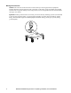
Moving the enclosure Casters. The enclosure can be moved on its casters with up to 1021 kg (2,250 lb) of equipment installed. Push the enclosure from the front or the back, not the sides; it may be unstable when pushed from the side. For greater stability, load 159 kg (350 lb) or more of equipment into the enclosure before moving it on its casters. ns0882b Eye bolts. If lifting of the enclosure is necessary, this can be done by attaching eye bolts (not included) to the top of the enclosure frame.
Installation Configuration Before installing the enclosure, plan the location and space needed to install equipment, and plan the ergonomics of keyboards and video monitors. The Rack Configurator, available on the APC Web site, www.apc.com, helps you plan your configuration to maximize the available U-space of your enclosures. Installing the Enclosure Warning: For extra stability, load 158 kg (350 lb) of equipment into the bottom of the enclosure before moving it on its casters.
Removing the casters and leveling feet (optional) Warning: To avoid personal injury or damage to the enclosure, two people should support the enclosure. The enclosure should be empty and the roof, side panels, and front and rear doors should be removed before laying the enclosure on its side. Tilt the enclosure in an area that will allow for proper clearance above the enclosure. 1. Lay the enclosure on its side. 2.
APC offers the following brackets for providing stabilization. Product Stabilizer Plate Kit Bolt-down Kit Pallet Mounting Bracket (provided) SKU Description AR7700 Attaches externally to the enclosure and floor to provide additional stability. AR7701 Attaches to enclosure and floor internally or externally to provide additional stability without blocking cable access. Figure Attaches to enclosure and floor internally or externally to provide additional stability.
Removing and Installing the Side Panels Remove the side panels to access the interior or pass cables between the enclosures when joining enclosures together. Side panels offer additional security and assist with proper airflow within the enclosure. Removing the side panels 1. Use the key to unlock the panel, if necessary. 2. Slide the panel latch down. 3. Pull the top of the panel away from the enclosure. na2591a 4.
Removing and Installing the Roof Removing the roof 1. Pull and hold the two spring pins in the rear of the enclosure. 2. Push the roof up from the enclosure. 3. Lift the roof off the enclosure. Installing the roof 1. Slide the tabs on the front of the roof into the slots in the front of the enclosure. 2. Lower the roof into the enclosure, while pulling the two spring pins in the rear of the roof. ns1452a 3. Release the pins to secure the roof to the enclosure.
Removing and Installing the Doors Note: If the enclosures are joined together, see “Removing the Doors of Joined Enclosures” on page 32. Warning: To avoid personal injury or damage to the enclosure, one person should support the door while another person removes the door from its frame. Removing the doors You can remove the front and rear doors of the enclosure to gain better access to equipment. 1. Disconnect the grounding wire. ns0928a 2.
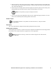
Reversing the front door 1. Remove the APC nameplate from the front door. ns1106a 2. Remove the M6 x 12 pan-head screws and star washers that secure the grounding wire to the frame and door, using the Torx T30/#2 Phillips wrench (provided). ns0176b 3. Remove the two Phillips screws from the rear of the door handle assembly, and remove the handle assembly from the door.
4. Remove the screw, latch, and washer from the back of the door handle assembly using the Torx T30/#2 Phillips wrench (provided). Rotate the washer 90 degrees and the latch 180 degrees and reattach the latch. 90° ns0910a ns0913a ns0912a 180° 5. Remove the door. See “Removing the doors” on page 12. 6. Remove the hinges from the frame using the Torx T30 /#2 Phillips wrench (provided). Rotate the hinges 180 degrees, and reinstall them on the other side of the frame of the enclosure.
ns0919a 7. Remove the hinges from the door and reinstall them using the set of holes directly below where they were originally installed. 8. Rotate the door 180 degrees and reinstall the door. See “Installing the doors” on page 12. ns0858a 9. Reinstall the grounding wire to the top of the door, near the hinges, and to the enclosure frame using the M6 x 12 pan-head screw and star washer. 10.Rotate the door handle assembly 180 degrees and reinstall it using the screws removed in step 2. 11.
Vertical Mounting Flanges ns1453a Vertical mounting flanges come factory-installed on the enclosure in the proper position for use with rack-mountable equipment that has a depth of 558.8 mm (22 in) and accommodates networking and telecommunications equipment. The mounting flanges are adjustable towards the front or the rear of the enclosure to accommodate different rails or equipment with other depths. The flanges can be adjusted to be as close as 279.4 mm (11 in) or as far as 870 mm (34.25 in) apart.
ns0717c 2. Lower the flat bracket and move the mounting flange to the desired location. ns0977b 1. Use the Torx T30/#2 Phillips wrench (provided) to loosen—but not remove—the Torx screws in the slots of each mounting flange. 3. To align the vertical mounting flanges properly, note the symbol (for example, the diamond) visible through one of the holes on the top of the flange, and ensure that the same symbol is visible through the corresponding hole at the bottom of the flange.
4. When the vertical mounting flange is in the proper location, slide each screw up until the teeth in the bracket engage fully with the teeth in the side brace, and tighten the screws. Installation accessories To install equipment that has a different mounting depth from the other equipment in the enclosure, use the appropriate APC Recessed Rail Kit. AR7508 for 42 U and AR7578 for 48 U, 750-mm enclosures.
Installing Equipment This section provides information on how to install rack-mount equipment in the NetShelter SX enclosure. The instructions provided with the equipment provide more detailed information. Note: APC NetShelter SX enclosures are intended for use with UL-Listed equipment. Installation of recognized components or otherwise un-listed equipment will require the user to evaluate the safety and flammability ratings of their configuration.
Installing cage nuts APC offers a cage nut hardware kit (AR8100) for use with square holes. Warning: Install cage nuts horizontally, with the ears engaging the sides of the square hole. Do NOT install cage nuts vertically with the ears engaging the top and bottom of the square hole. 1. Insert the cage nut into the square hole by hooking one ear of the cage nut assembly through the far side of the hole. Note: Install the cage nuts on the interior of the vertical mounting flange. 2.
Grounding The doors, side panels, and roof of the enclosure are grounded to the enclosure frame. The doors are grounded with quick-disconnect cables. The roof and side panels are inherently grounded through spring fingers. Each enclosure should be grounded directly to the building ground using one of the M6 grounding nuts at the base of the enclosure. ns0905a ns0906a Ground each enclosure directly to the building ground. Do not ground one enclosure to another enclosure in a cascading style.
Airflow management ns1548b Equipment with side airflow requirements Side Airflow Duct Kit. For networking switch applications, APC offers a Side Airflow Duct Kit (AR7715).The Side Airflow Duct Kit allows for improved cable management solutions while maintaining adequate airflow and separation of hot and cold aisles to cool switches.The Side Airflow Duct Kit maintains separation of hot and cold aisles via ducts and baffle panels.
Install the ducts and adjustable side baffle. Complete the installation by installing the foam gaskets to close any gaps between the side panel and duct kit. The duct kit and gaskets when properly installed direct cold airflow into the networking switch. ns1567a Caution: Do not obstruct the area in front of the ducts. This is the cold air intake and air needs to flow freely for proper operation of the side airflow duct kit.
Airflow management panels. Foam airflow management panels are provided to install between the vertical mounting flange and enclosure side panel to provide isolation of hot air and prevent it from entering the cold aisle. To ensure proper airflow into the networking switches install the airflow management panels besides inactive equipment such as data distribution panels and keep the air intake clear besides networking switches and in front of the side airflow duct kit.
Data Distribution The 1-U and 2-U Data Distribution Panels are TIA-EIA-310-D-compliant and can be mounted on the front or rear rails of an APC NetShelter or any other standard enclosure. ns1564a Installation Install four caged nuts (two per side) into the upper- and lower-most holes at the desired mounting location in the enclosure. Secure the Data Distribution Panel in place using four M6 screws and four plastic cup washers (two per side).
Cable Management The NetShelter SX Networking Enclosure has cable access openings on its roof, sides, and bottom. Four vertical cable organizers and two Vertical 0U Accessory Channels are included with the enclosure and APC offers a variety of other cable management accessories. Vertical 0U Accessory Channels The vertical 0-U accessory channels attach to the enclosure along the side braces.
Cable management options Product SKU Description Figure AR8602 (1 U) 19-inch 1-U cable passthrough with brush strip Cable containment brackets Side panel with access holes Zero-U accessory mounting bracket AR8603 (2 U high density) Route patch cables horizontally at the front or rear of a 19-inch EIA enclosure. AR8429 Assists with containing air in the enclosure. AR7710 Contains cables along the vertical 0U accessory channel and is installed without tools. Quantity of six.
Product Vertical cable manager Vertical Cable Organizer for NetShelter 0-U Accessory Channel Narrow vertical 0-U accessory channel for 42-U enclosure 28 SKU Description AR7717 Contains cables along the vertical mounting flanges and also mounts in the vertical 0-U accessory channel. The vertical cable manager has smooth plastic fingers at 1U increments to allow patch cords to enter and exit in an organized manner. Quantity of four.
Fiber organizer (spools only) Toolless Hook-andLoop Cable Managers AR8443A The vertical fiber organizer and fiber organizer spools provide a method to manage fiber cabling within an enclosure and mount toollessly into the vertical 0U accessory channel of the enclosure. Quantity of two. AR8444 Can be mounted toollessly to the vertical fiber organizer or attached with screws to the mounting rails of 750-mm wide enclosures. Quantity of four.
Joining Enclosures Joining the Enclosures You can expand your installation by joining two enclosures together. All enclosures include pre-installed joining hardware. Caution: Joining enclosures together does not provide additional stability to the enclosures. Note: NetShelter SX enclosures can be joined with or without side panels installed. 1. Remove the front doors from the enclosures if necessary. See “Removing the doors” on page 12. ns0618b 2.
3. The enclosures can be joined so that their centers are 30 in or 750 mm apart. Align the enclosures to use the appropriate holes on the front and rear of the enclosures for the spacing you need and secure the enclosures using one M5 x 12 flat-head screw per bracket. 30 in ns1538a 750 mm 4. If the enclosures are joined together on 30-in centers, there is a gap between them. APC offers optional baying trim (AR7600) to cover the gap between the enclosures.
Removing the Doors of Joined Enclosures If enclosures are joined together, the door removal process is slightly different than on a single enclosure. Follow these steps to remove either a front or rear door from an enclosure that is joined to another enclosure. 1. Open the door you wish to remove to a 90 degree angle. The door will not open any farther than this because of the enclosure next to it. 90° ns1039a 2. Lift the door upward. 60° ns1040a 3.
Specifications 750-mm, 42-U Enclosures Measurements Item AR3140 Height 1991 mm (78.40 in) Width 750 mm (29.53 in) Depth 1070 mm (42.13 in) Net weight 155.95 kg (343.10 lb) Total open area (front door) 788 972 mm2 (1,222.91 in2) Total open area (rear door) 866 920 mm2 (1,343.73 in2) Open area per U (front door) 18 787 mm2 (29.
Five-Year Factory Warranty The limited warranty provided by American Power Conversion (APC®) in this Statement of Limited Factory Warranty applies only to products you purchase for your commercial or industrial use in the ordinary course of your business. Terms of warranty APC warrants its products to be free from defects in materials and workmanship for a period of five years (two years in Japan) from the date of purchase.
IN NO EVENT SHALL APC, ITS OFFICERS, DIRECTORS, AFFILIATES OR EMPLOYEES BE LIABLE FOR ANY FORM OF INDIRECT, SPECIAL, CONSEQUENTIAL OR PUNITIVE DAMAGES, ARISING OUT OF THE USE, SERVICE OR INSTALLATION, OF THE PRODUCTS, WHETHER SUCH DAMAGES ARISE IN CONTRACT OR TORT, IRRESPECTIVE OF FAULT, NEGLIGENCE OR STRICT LIABILITY OR WHETHER APC HAS BEEN ADVISED IN ADVANCE OF THE POSSIBLY OF SUCH DAMAGES.
APC Worldwide Customer Support Customer support for this or any other APC product is available at no charge in any of the following ways: • Visit the APC Web site to access documents in the APC Knowledge Base and to submit customer support requests. – www.apc.com (Corporate Headquarters) Connect to localized APC Web sites for specific countries, each of which provides customer support information. – www.apc.com/support/ Global support searching APC Knowledge Base and using e-support.