Unpacking, Installation, and Customization Manual NetShelter™ SX Enclosure
This manual is available in English on the enclosed CD. Dieses Handbuch ist in Deutsch auf der beiliegenden CD-ROM verfügbar. Este manual está disponible en español en el CD-ROM adjunto. Ce manuel est disponible en français sur le CD-ROM ci-inclus. Questo manuale è disponibile in italiano nel CD-ROM allegato. 本マニュアルの日本語版は同梱の CD-ROM からご覧になれます。 Instrukcja Obsługi w jezyku polskim jest dostepna na CD. O manual em Português está disponível no CD-ROM em anexo.
Contents Introduction ..................................................................... 1 Unpacking the Enclosure ............................................... 2 Disclaimer . . . . . . . . . . . . . . . . . . . . . . . . . . . . . . . . . . . . . . . . . . . . . . 2 Receiving inspection . . . . . . . . . . . . . . . . . . . . . . . . . . . . . . . . . . . . . 2 Please Recycle . . . . . . . . . . . . . . . . . . . . . . . . . . . . . . . . . . . . . . . . . . 2 Component Identification................
Equipment Installation .................................................. 15 Adjusting Vertical Mounting Flanges . . . . . . . . . . . . . . . . . . . . . . . . 15 Installing Equipment . . . . . . . . . . . . . . . . . . . . . . . . . . . . . . . . . . . . . 18 Removing Cable Cutout Covers . . . . . . . . . . . . . . . . . . . . . . . . . . . . 19 Accessories. . . . . . . . . . . . . . . . . . . . . . . . . . . . . . . . . . . . . . . . . . . . . 20 Recessed rail kits . . . . . . . . . . . . . . . . . . . .
Specifications ................................................................ 31 42 U Enclosures. . . . . . . . . . . . . . . . . . . . . . . . . . . . . . . . . . . . . . . . . .31 45 U Enclosures. . . . . . . . . . . . . . . . . . . . . . . . . . . . . . . . . . . . . . . . . .33 48 U Enclosures. . . . . . . . . . . . . . . . . . . . . . . . . . . . . . . . . . . . . . . . . .35 APC Limited Factory Warranty..................................... 37 Terms of Warranty . . . . . . . . . . . . . . . . . . .
Introduction The American Power Conversion (APC™) NetShelter SX 600 mm (23.6 in) and 750 mm (29.5 in) wide enclosures are high-quality enclosures for storage of industry-standard (EIA/ECA-310), 19 in (483 mm) rack-mount hardware, which includes servers and voice, data, networking, internetworking, and APC power protection equipment. Optional vertical mounting flanges are available for the 750 mm (29.5 in) wide enclosure for accommodating 23 in EIA/ECA telecommunications equipment.
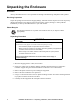
Unpacking the Enclosure Disclaimer APC by Schneider Electric is not responsible for damage sustained during reshipment of this product. Receiving inspection Inspect the package and contents for shipping damage, and make sure that all parts were sent. Report any damage immediately to the shipping agent. Report missing contents, damage, or other problems immediately to APC by Schneider Electric or your APC reseller. Please Recycle The shipping materials are recyclable.
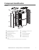
Component Identification ns0609b Enclosure Adjustable vertical 0 U accessory channel* Removable and reversible front door Removable rear split doors APC nameplate Removable side panel with lock Key for doors and side panels Enclosure frame Vertical mounting flanges Adjustable leveling feet 1070 mm (42.13 in) roof Hardware bag (see page 4) Casters 1200 mm (47.24 in) roof * 1200 mm (47.24 in) deep enclosures include four vertical 0 U accessory channels.
Hardware bag contents Plastic cup washers (60) M6 x 16 Phillips slot screws (60) M5 x 12 screws (4) Torx® T30/#2 Phillips wrench (1) 4 Cage nuts (60) 7-mm (0.
Removing and Reinstalling Side Panels, Roof, and Doors na2591a Side Panels Roof NetShelter SX Enclosure — Unpacking, Installation, and Customization Manual 5
Doors Doors self-align on hinge pins when properly installed. ns1750b 1. With the door at a 90-degree angle to the front of the enclosure, position the door over the hinge pins ( ). ns1751b 2. Use slight pressure to pull the door away from enclosure; then lower the door. ns1752b 3. Connect the ground wire.
Enclosure Installation Moving the Enclosure WARNING TIP HAZARD This enclosure is easily tipped. Use extreme caution when unpacking or moving. • Use at least two people to unpack and move the enclosure. • Before moving the enclosure on its casters, load 158 kg (350 lbs) of equipment into the bottom of the enclosure for extra stability. • When moving on its casters, make sure the leveling feet are up and push the enclosure from the front or rear.
Leveling Rack-Based Equipment Note: The leveling feet provide a stable base if the floor is uneven, but cannot compensate for a badly sloped surface. Note: To allow the equipment to rest directly on the floor the casters and leveling feet can be removed. The front and rear doors may need to be removed. See the section elsewhere in this manual for removal and installation instructions. 1. Using a screw driver or 13 mm wrench lower each leveling foot until in makes contact with the floor. na1572a 2.
Joining Enclosures Enclosures can be joined with or without side panels installed to provide for alignment and some stability. WARNING TIP HAZARD Joining enclosures provides limited stability to the enclosures. Make sure you secure the enclosure to the floor before installing equipment. Failure to follow these instructions can result in serious injury or equipment damage. 1. Remove the front and rear doors. 2. Choose between 24 in centers or 600 mm centers (see the detail view below). 3.
Reversing the Front Door You can reverse the front door so the door is hinged on the opposite side. Required tools: Torx® T30/#2 Phillips wrench (provided in hardware bag) ns1758b 1. Remove the handle. ns1752b 2. Disconnect the ground wire and then remove the door.
ns1824a 3. Remove and reinstall the hinges on the enclosure frame. ns1825a 4. Remove and reinstall the hinges in the door frame. 5. Reinstall door and reconnect the ground wire. ns1766b 6. Remove and reinstall the latch and washer oriented as shown. The washer is rotated 90 degrees from its original orientation, and the latch is rotated 180 degrees.
ns1779b 7. Reinstall the handle on the door. 8. Remove and reinstall the APC nameplate at the location shown.
Securing the Enclosure WARNING TIP HAZARD Make sure you secure the enclosure to the floor before installing equipment. Failure to follow these instructions can result in serious injury or equipment damage. To secure the enclosure to the floor, use fastener locations on the outside or inside of the enclosure, and choose from the accessories shown below.
Grounding the Enclosure Each enclosure should be bonded directly to a common ground using one of the designated grounding locations (two M6 threaded inserts) at the top or bottom of the enclosure. • Use a Common Bonding Network Jumper kit (for example, Listed [KDER] Panduit® RGCBNJ660PY or equivalent) • Use paint-piercing washers between ground terminal and enclosure frame or remove paint on frame under ground terminals per NEC NFPA 70 Article 250.12 • Torque screws to 6.
Equipment Installation Note: APC NetShelter SX enclosures are intended for use with Listed equipment. If you install un-Listed equipment, you should evaluate the safety of your configuration. Adjusting Vertical Mounting Flanges Vertical mounting flanges come factory-installed in the proper location for use with rack-mountable equipment that has a depth of 737 mm (29 in).
To adjust a vertical mounting flange: WARNING FALLING EQUIPMENT When adjusting vertical mounting flanges, do so with no equipment installed on the vertical mounting flanges. Failure to follow these instructions can result in serious injury or equipment damage. 1. Use the Torx T30/#2 Phillips wrench (provided) to loosen—but not remove—the Torx screws at the top, middle, and bottom of the vertical mounting flange.
2. Lower the three flat brackets and move the mounting flange to the desired location. – On the 750 mm (29.5 in) rack there are circles 476 mm (18.75 in) behind the front mounting flange designating the location for the rear vertical mounting flanges when installing networking and telecommunications equipment. ns0717a – Vertical mounting flanges adjust in 6-mm (1/4-in) increments. 3.
Installing Equipment WARNING TIP HAZARD This enclosure is easily tipped. Follow the precautions below during and after equipment installation. • Make sure you have secured the enclosure to the floor before installing equipment. • Install the heaviest equipment first toward the bottom of the enclosure to prevent the enclosure from becoming top-heavy.
Removing Cable Cutout Covers For NetShelter SX 750 mm (29.5 in) wide enclosures that include equipment requiring side airflow, on the side of the enclosure nearest the air intake for the equipment (left side in the example below), remove the cable cutout covers from the front vertical mounting flange. Reinstall the covers in the cable cutout holes on the rear vertical mounting flange on the same side of the enclosure.
Accessories Recessed rail kits Allows for the installation of equipment with different mounting depths than the equipment installed on the factory-supplied vertical mounting flanges.
Cable Management Route, secure, and organize cables using the multiple cable access openings on the enclosure roof, sides, and bottom, the vertical 0 U accessory channels included with the enclosure, plus the variety of cable management accessories available. Adjusting the Vertical 0 U Accessory Channels The vertical 0 U accessory channels [four included with the 1200 mm (47.
Accessories Cable Management Rings (AR8113A) Includes five large and five small rings. Fastens cables to posts, mounting rails, or braces. 19 in Horizontal Cable Organizer Routes cables horizontally on the front or back of the 19 in EIA rack. The following models are available: • 1 U Horizontal Cable Organizer (AR8425A) • 2 U Horizontal Cable Organizer (AR8426A) 19 in, 2 U Patch Cord Organizer (AR8427A) Routes cables horizontally on the front or back of the 19 in EIA rack.
19 in, 1 U Cable Pass-through with Brush Strips (AR8429) Assists with containing air in the enclosure. Cable Containment Brackets (AR7710) Includes six brackets. Brackets contain cables along the vertical cable organizer and allow the installation on Rack Power Distribution Units on the front or sides of the bracket. Brackets install without tools. Includes five pieces. Replacement brush strips that install in NetShelter roof and side panels to help ensure proper airflow.
0 U Accessory Mounting Bracket (AR7711) Includes two brackets. Installs in various locations within the enclosure; for example, on the vertical mounting flanges and on the vertical 0 U accessory channels. Provides mounting options for Rack PDUs and other small accessories. Center, Rear-Mount Vertical Cable Orgnaizer (AR7505) Allows cable routing or Rack PDU installation vertically in the rear of the enclosure.
0 U, 8 Cable Rings, Vertical Cable Organizer (AR8442) Includes two pieces. Eliminates cable stress by organizing cable layout within the rear channels of the enclosure. Uses 0 U space within the enclosure. Consists of two pieces of equal size. You can install both vertical cable organizers side by side in a vertical 0 U accessory channel or stack each piece to span the entire height of the enclosure.
Narrow Vertical 0 U Accessory Channel (AR7511) ns1754b Includes two pieces. The narrow vertical 42 U, 0 U accessory channel compliments the standard vertical 0 U accessory channel by offering additional cable management options. The narrow channel can be used in the front of the enclosure to mount fiber cable spools and vertical cable managers or it can be used in the middle of the enclosure for cable tie off. In addition, keyholes are provided to mount one vertical Rack PDU per organizer.
Fiber Organizer Spools (AR8444) ns1854a Includes four pieces. Can be mounted toollessly to a vertical 0 U accessory channel or to any 9.5 x 9.5 mm (0.375 x 0.375 in) square hole using a cage nut and a screw. Brush Strip Kit (AR7706) ns1034b Includes six pieces. The 750 mm wide enclosure features openings in the front vertical mounting flanges for cable routing. These openings are sealed with factory-installed plastic covers to restrict airflow.
1 U Cable Rings (AR7707) Includes eight cable rings. Fastens cables to the vertical mounting rails of the enclosure. For use with 750 mm enclosures in networking applications. Air Recirculation Prevention Kit (AR7708) ns106 5b Includes cable routing covers and airflow restriction strips. Prevents the recirculation of warm air exhaust inside the enclosure by closing gaps between the vertical mounting flanges and the side panels.
Cable management accessory to help eliminate cable stress and maintain a neat, organized cable layout within an enclosure or rack.
NetShelter SX Accessory Compatibility 30 3 3 3 3 3 3 3 3 3 3 3 3 3 3 3 3 3 3 3 3 3 3 3 3 3 3 3 3 3 AR3357 AR3307 AR3157 AR3107 AR3355 AR3305 AR3155 AR3105 AR3350 AR3300 AR3150 Accessory AR7503 - Recessed Rail Kit, 42 U, 600 mm wide AR7504 - Recessed Rail Kit, 48 U, 600 mm wide AR7508 - Recessed Rail Kit, 42 U, 750 mm wide AR7578 - Recessed Rail Kit, 48 U, 750 mm wide AR7510 - 23 in EIA Mounting Rails for 750 mm wide enclosures AR8113A - Cable Management Rings AR8425A - 1 U Horizontal C
Specifications 42 U Enclosures AR3100 AR3150 Height 1991 mm (78.39 in) 1991 mm (78.39 in) Width 600 mm (23.62 in) 750 mm (29.53 in) Depth 1070 mm (42.13 in) 1070 mm (42.13 in) Net weight 125.09 kg (275.20 lb) 155.96 kg (343.10 lb) Total open area front door 593 018 mm2 (919.18 in2) 788 972 mm2 (1,222.91 in2) Total open area rear door 669 276 mm2 (1,037.38 in2) 866 920 mm2 (1,343.73 in2) Open area per U front door 14 129 mm2 (21.90 in2) 18 787 mm2 (29.
42 U Enclosures, continued AR3300 AR3350 Height 1991 mm (78.39 in) 1991 mm (78.39 in) Width 600 mm (23.62 in) 750 mm (29.53 in) Depth 1200 mm (47.24 in) 1200 mm (47.24 in) Net weight 134.09 kg (295.00 lb) 161.36 kg (355.00 lb) Total open area front door 593 018 mm2 (919.18 in2) 788 972 mm2 (1,222.91 in2) Total open area rear door 669 276 mm2 (1,037.38 in2) 866 920 mm2 (1,343.73 in2) Open area per U front door 14 129 mm2 (21.90 in2) 18 787 mm2 (29.
45 U Enclosures AR3105 AR3155 Height 2124 mm (83.62 in) 2124 mm (83.62 in) Width 600 mm (23.62 in) 750 mm (29.53 in) Depth 1070 mm (42.13 in) 1070 mm (42.13 in) Net weight 137 kg (301.40 lb) 155 kg (341 lb) Total open area front door 635 373 mm2 (984.83 in2) 847 212 mm2 (1313.18 in2) Total open area rear door 715 693 mm2 (1109.33 in2) 929 528 mm2 (1440.77 in2) Open area per U front door 14 119 mm2 (21.89 in2) 18 827 mm2 (29.18 in2) Open area per U rear door 15 904 mm2 (24.
45 U Enclosures, continued AR3305 AR3355 Height 2124 mm (83.62 in) 2124 mm (83.62 in) Width 600 mm (23.62 in) 750 mm (29.53 in) Depth 1200 mm (47.24 in) 1200 mm (47.24 in) Net weight 141 kg (310.2 lb) 169 kg (371.8 lb) Total open area front door 635 373 mm2 (984.83 in2) 847 212 mm2 (1313.18 in2) Total open area rear door 715 693 mm2 (1109.33 in2) 929 528 mm2 (1440.77 in2) Open area per U front door 14 119 mm2 (21.89 in2) 18 827 mm2 (29.
48 U Enclosures AR3107 AR3157 Height 2258 mm (88.90 in) 2258 mm (88.90 in) Width 600 mm (23.62 in) 750 mm (29.53 in) Depth 1070 mm (42.13 in) 1070 mm (42.13 in) Net weight 138.23 kg (304.10 lb) 169.09 kg (372 lb) Total open area front door 676 805 mm² (1,049.05 in²) 900 417 mm2 (1,395.65 in2) Total open area rear door 763 637 mm² (1,183.64 in²) 989 243 mm2 (1,533.33 in2) Open area per U front door 14 103 mm² (21.86 in²) 18 761 mm2 (29.08 in2) Open area per U rear door 15 909 mm²(24.
48 U Enclosures, continued AR3307 AR3357 Height 2258 mm (88.90 in) 2258 mm (88.90 in) Width 600 mm (23.62 in) 750 mm(29.53 in) Depth 1200 mm (47.24 in) 1200 mm (47.24 in) Net weight 149.55 kg (329.00 lb) 185.45 kg (408 lb) Total open area front door 676 805 mm² (1,049.05 in²) 900 417 mm2 (1,395.65 in2) Total open area rear door 763 637 mm² (1,183.64 in²) 989 243 mm2 (1,533.33 in2) Open area per U front door 14 103 mm² (21.86 in²) 18 761 mm2 (29.
APC Limited Factory Warranty The limited warranty provided by American Power Conversion (APC®) in this Statement of Limited Factory Warranty applies only to Products you purchase for your commercial or industrial use in the ordinary course of your business. Terms of Warranty American Power Conversion warrants its products to be free from defects in materials and workmanship for a period of five years (two years in Japan) from the date of purchase.
IN NO EVENT SHALL APC, ITS OFFICERS, DIRECTORS, AFFILIATES OR EMPLOYEES BE LIABLE FOR ANY FORM OF INDIRECT, SPECIAL, CONSEQUENTIAL OR PUNITIVE DAMAGES, ARISING OUT OF THE USE, SERVICE OR INSTALLATION, OF THE PRODUCTS, WHETHER SUCH DAMAGES ARISE IN CONTRACT OR TORT, IRRESPECTIVE OF FAULT, NEGLIGENCE OR STRICT LIABILITY OR WHETHER APC HAS BEEN ADVISED IN ADVANCE OF THE POSSIBLY OF SUCH DAMAGES.
APC Worldwide Customer Support Customer support for this or any other APC product is available at no charge in any of the following ways: • Visit the APC Web site to access documents in the APC Knowledge Base and to submit customer support requests. – www.apc.com (Corporate Headquarters) Connect to localized APC Web sites for specific countries, each of which provides customer support information. – www.apc.com/support/ Global support searching APC Knowledge Base and using e-support.