Installation, Operation, and Maintenance NetworkAIR® Portable Air Conditioning Unit ACPA4000
American Power Conversion Legal Disclaimer The information presented in this manual is not warranted by the American Power Conversion Corporation to be authoritative, error free, or complete. This publication is not meant to be a substitute for a detailed operational and site specific development plan.
Contents General Information ........................................................ 1 Overview . . . . . . . . . . . . . . . . . . . . . . . . . . . . . . . . . . . . . . . . . . . . . . . . 1 About the NetworkAIR ACPA4000 . . . . . . . . . . . . . . . . . . . . . . . . . . . 1 Save these instructions . . . . . . . . . . . . . . . . . . . . . . . . . . . . . . . . . . . 1 Manual updates . . . . . . . . . . . . . . . . . . . . . . . . . . . . . . . . . . . . . . . . . .
Relays and Contacts . . . . . . . . . . . . . . . . . . . . . . . . . . . . . . . . . . . . . 13 Overview . . . . . . . . . . . . . . . . . . . . . . . . . . . . . . . . . . . . . . . . . . . . . . . 13 Output relays . . . . . . . . . . . . . . . . . . . . . . . . . . . . . . . . . . . . . . . . . . . 13 Input contacts . . . . . . . . . . . . . . . . . . . . . . . . . . . . . . . . . . . . . . . . . . 14 Start-Up . . . . . . . . . . . . . . . . . . . . . . . . . . . . . . . . . . . . . . . . . . . . . . .
Checking Equipment Status. . . . . . . . . . . . . . . . . . . . . . . . . . . . . . . .27 Scrolling status screens . . . . . . . . . . . . . . . . . . . . . . . . . . . . . . . . . . 27 Default schedule status . . . . . . . . . . . . . . . . . . . . . . . . . . . . . . . . . . . 27 System and environmental status screens . . . . . . . . . . . . . . . . . . . 27 Manufacturer data . . . . . . . . . . . . . . . . . . . . . . . . . . . . . . . . . . . . . . . 28 Viewing alarm status . . . . . . . . . . . . . .
General Information Overview About the NetworkAIR ACPA4000 Your NetworkAIR ACPA4000 is a portable, compact air conditioner designed for spot-cooling, emergency-cooling, and after-hours cooling of server closets, data centers, conference rooms, home offices, or rooms that house heat-sensitive equipment. The ACPA4000 provides 3.8 kWh (13,000 BTU) of cooling power. It automatically adjusts room temperature and reduces moisture while filtering the air.
Safety symbols that may be used in this manual Electrical Hazard: Indicates an electrical hazard which, if not avoided, could result in injury or death. Danger: Indicates a hazard which, if not avoided, could result in severe personal injury or substantial damage to product or other property. Warning: Indicates a hazard which, if not avoided, could result in personal injury or damage to product or other property. Heavy: Indicates a heavy load that should not be lifted without assistance.
Safety Warning: Use the equipment on a flat surface. Do not obstruct the equipment air outlets. For indoor use only. Do not attempt to service the equipment except to clean and replace the air filters. The equipment contains no other user-serviceable parts. Do not place the rear of the equipment closer than 203 mm (8 in) to any wall or obstacle. Do not install the equipment where there are fumes or flammable gases, or in an extremely humid space such as a greenhouse. Do not place this equipment on its side.
Tools Required Nutdriver–M6 Pliers Wire cutters Inventory na0148a The equipment ships with the items shown below: Portable air conditioner Terminal blocks Ceiling adapter Remote temperature sensor–3.66 m (12 ft) Air deflector Power cord - Leakage Current Detection Interruptor (LCDI)–2.40 m (8 ft) M6 nuts Communication cable–2 m (6.50 ft) Duct collars Quick-connect fitting Ducts Drain line–15.24 m (50 ft) This equipment requires an LCDI plug.
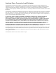
Component Identification na0118c Front view Condenser air intake Locking casters (front 2 casters only) Condenser exhaust Access panel (for use by service personnel only) Display interface na0119c Rear view Replaceable air filter element Main control board Drain line connector Communication port, RS-232 connector Detachable power cord–2.
na2462a Dimensions and Weights Dimensions are shown in mm (in).
Installation Where to locate the equipment When deciding where to locate the equipment, consider your cooling needs, air flow, the location of the electrical outlet (no more than 2.4 m (8 ft) from the equipment), and access for the condenser intake and exhaust. Cooling needs. Position the equipment as close as possible to the main source of heat that requires cooling. Location of electrical outlet. Place the equipment no farther than 2.4 m (8 ft) from a dedicated 115V, 60Hz, 20A branch circuit receptacle.
Intake and Exhaust Vents Hose connections The equipment requires the installation of intake and exhaust ducts for the condenser. See the drawing to identify the intake and exhaust sides of the equipment. Building structural support 10-gauge (minimum) steel wire Ceiling adapter Air deflector Condenser exhaust duct na0418a Condenser air intake duct Assemble the ceiling adapter Caution: The air deflector must face away from the air intake and obstructions such as walls or piping.
Install the adapter in a drop ceiling Use the ceiling adapter to provide an intake and exhaust outlet for the condenser. Note: Allow at least 305 mm (12 in) of open space above the ceiling adapter opening so exhaust air is not blocked. 1. Determine a location to install the ceiling adapter. 2. Remove the ceiling tile in the chosen location and save it for a future step. na0373a 3. Place the ceiling adapter into the ceiling tile grid. na0397a 4.
Assemble the ducts 1. Thread the duct collars counterclockwise onto each of the ducts until they bottom out. na0312a Note: The hoses used are directional and reduce airflow if not properly installed. Expand the length of hose to fit the required space. 2. Install each hose so that the leading edge of the compressed section of the hose matches air direction flow. na1235a Air Flow 3. Slide the duct collar of each hose over the ceiling adapter sleeves and turn the duct collar to lock in place.
Drain Line The equipment contains an on-board condensate pump for automatic condensate removal.The equipment ships with 15.24 m (50 ft) of hose and a quick-connect fitting for removing condensate. You can attach a different hose to the equipment if you follow these requirements: • You must use a 6-mm (1/4-in) outside diameter (OD), clear, polyurethane hose. • The hose length must not exceed 15.24 m (50 ft), and 4.88 m (16 ft) vertical maximum.
Accessories Temperature/humidity sensor The Remote Temperature/humidity sensor (AP9512TH) monitors the room temperature and relative humidity. This remote sensor monitors the environment surrounding the cooling equipment to ensure that the conditioned air is cooling the desired area. Note: The equipment cannot be controlled based on the temperature measured by the sensor. To install the sensor: 1. Determine a location that allows you to neatly route and secure the 3.
Relays and Contacts Overview The controller board provides connectors for output relays and input contacts. The connectors can be used with any dry-contact sensors. The connectors are designed to monitor circuits that have no voltage potential of their own. Connecting the contact or relay to any circuit other than a dry closure connector may result in damage to the main control board.
To connect an output relay: 1. Attach a 12-position terminal block (provided) to the output relay connector. 2. Strip the wire insulation on the sensor 6 mm (0.25 in) from the end. 3. Connect your sensor wires to the pins associated with one of the four positions on the output relay connector. 4. Configure the settings for the output relay through the display interface. See “Set Up Contacts and Relays” on page 26.
Start-Up Start-up checklist Before starting the equipment, check to see that the following conditions are met: • All electrical connections comply with national and local codes and safety standards. • All accessories and ductwork have been installed. • Air flow to and from the equipment is not blocked. • The condensate drain is connected and not kinked or pinched. How to apply power to the equipment Insert the IEC-320-C19 connector of the power cord into the back of the equipment.
Operation Overview Display interface identification System On ? Minor Alarm Major Alarm 16 na0137a ESC Check Log Item Function Major Alarm LED When red, a major alarm condition exists. Minor Alarm LED When orange, a minor alarm condition exists. Check Log LED When orange, at least one new alarm or warning event has occurred. System On LED When green, the evaporator blower is running. Liquid Crystal Display (LCD) Shows alarms, status data, instructional help, and setup items.
How to Use the Interface All settings are controlled through the display interface located on the front of the equipment. Turn on the equipment After you plug in the power cord, the equipment immediately begins operation based on its last programmed settings. Note: The equipment waits three minutes before engaging the compressor if it has been unplugged or has been off for less than three minutes.
Main menu screen Main Menu Status ON / OFF Setup Alarms & Logging Control Environment na1268a On any of the scrolling status screens, press the ENTER or ESC key to open the main menu screen. Note: After the display interface is inactive for a configured period of time (time-out delay), it reverts to the scrolling status screens. To change the time-out delay setting, see “Password and time-out” on page 23. Navigating the interface Selector arrows.
Change settings To change a setting, use the up or down arrow keys to move the selector arrow to the setting and press the ENTER key. List of choices. If the setting is a list of choices, an input arrow is displayed next to the setting. Press the up or down arrow key to make your selection. Press the ENTER keys to save the setting and exit from input mode. Press the ESC key to exit without saving. Numbers or text fields.
Set Environmental Controls The equipment controls the environment through the use of schedules. There are nine schedules; one schedule has default settings and the other eight schedules are programmable. Cooling during the times and days for which there is no programmed schedule is performed according to the default schedule (Control Environment). Default schedule Path: Main menu > Control Environment. The default schedule controls cooling when other schedules are not available or are deactivated.
Operating schedules Path: Main Menu > Setup > Operating Schedule. Program up to eight sets of environmental controls that run according to the time and day. Scheduling: on/off. Select Off to use the default schedule, or On to use the programmed schedules. Reset schedules. Turn all schedules off and reset them to their factory default settings. Edit schedules. Set the cooling options for up to eight time periods. Schedule: 1 of 8 Select a schedule to modify.
Set Up Alarms The Portable Air Conditioning Unit is equipped with user-definable alarms. Set these alarms to alert you to abnormally high or low temperature and humidity. Alarms also alert you to malfunctions; however, malfunction alarms are not user-definable. See “Responding to Alarms” on page 29 for information on responding to alarms. Temperature and humidity alarms Path: Main Menu > Alarms & Logging > Alarm Setup > Temperature Limits or > Humidity Limits. Temperature Limits.
Set Up the Display The display interface provides access to the data and settings necessary to operate the equipment. Use the display interface to control data displayed, configure security features, and update and upgrade the firmware that controls the equipment. Password and time-out Path: Main Menu > Setup > System > System Password. Note: The default password is APC. See “Password entry” on page 19 for information on how to enter the password. Change the password: 1.
Device settings Path: Main Menu > Setup > System > Device. Temperature Units. Set the units of measure for temperature readings and settings. Start Delay. Set the delay between equipment start and when cooling begins. This delay is in addition to the start-up delay described in “Turn on the equipment” on page 17. Resetting to default settings Path: Main Menu > Setup > Factory Defaults. Reset to factory defaults. Resetting to factory defaults returns display options to their factory settings.
How to download firmware Path: Main Menu > Setup > Firmware Updates. To download firmware: 1. Go to www.apc.com/tools/download/ and check for the most recent version of the firmware. 2. If a newer version is available, download it to a location that can be accessed in step 5. 3. Set up the serial connection: a. Connect an available serial port of your computer to the serial port on the back of the unit using the supplied serial cable. b. Run a terminal emulation program, such as Windows® HyperTerminal. c.
Set Up Contacts and Relays Input contacts can be set to trigger an alarm if their current state changes from the user-defined normal state. Output relays can map internal alarms and events to external devices. Input contacts Path: Main Menu > Status > Contact I/O > Inputs. There is one predefined input contact that can be configured: Remote Stop. Change the normal state. Move the selector arrow to the Normal option and press the ENTER key.
Checking Equipment Status The Portable Air Conditioning Unit has several options for viewing the status of the equipment and the environment being cooled. Temperature and humidity readings and the detailed status of the equipment are available through the display interface.
Manufacturer data Path: Main Menu > Setup > Manufacturer Data. APC preprograms your display with information that is helpful when obtaining service. The information provided includes: • Manufacturer Name • Model Number • Serial Number • Firmware Revision • Hardware Revision • Date of Manufacture Viewing alarm status Path: Main Menu > Alarms & Logging. View active alarms. Displays all active alarm conditions. Alarm/Event log.
Responding to Alarms When an alarm condition is triggered, the Portable Air Conditioning Unit alerts you through the: • Alarm beeper • Alarm or warning LED • Active alarm screen • Alarm/Event log Depending on the severity of the alarm, you may need to take action to clear the alarm condition or to resume operation. See “Alarm messages” on page 31 for a listing of alarms and the actions required to clear them. Silencing the alarm beeper Path: Main Menu > Alarms & Logging > Alarm Beeper.
Active alarm screen Path: Main Menu > Alarms & Logging > View Active Alarms. The active alarms screen is available at the above path or on the scrolling status screens. View the number of alarms (e.g., 1of 2) and a description of the alarm condition. Alarm and event log Path: Main Menu > Alarms & Logging > Alarm/Event Log. The alarm/event log lists each alarm condition and the date and time it occurred. Viewing either the New Logged Items or the Entire Log deactivates the Check Log LED.
Alarm messages Alarm Message Action Required High head pressure Ensure condenser exhaust air diverter is not blocked, facing a wall, or pointed at the condenser air inlet. Check the area above the ceiling where the condenser air is circulating for excessive heat buildup. Additional ventilation may be required. Check the condenser inlet filter for cleanliness. Supply temperature high Alarm setpoint may be too low. Alarm should normally be set to 10° (C or F) above the cool setpoint plus the dead band.
Alarm Message Action Required Remote temperature high Alarm setpoint may be too low. Check the sensor placement. Ensure that the sensor is able to sense the cool supply air from the unit. Check that the sensor is not near a direct heat source such as an equipment discharge fan, a room supply duct, a window, direct sunlight, or a room entrance. Equipment capacity may be too small for room load. Check that the equipment is cooling.
Display Interface Reference Charts Scrolling status screens System Status Blower: High System Status Power: ON Mode: Cool Setpoint: 65 ° F No Active Alarms System Time: Month-day year Default schedule is active System Time: Month-day year Time Time na1286a Temp & Humidity Supply: 62 ° F Return: 76 ° F Remote: 75 ° F 13 % Monitoring information Status Menu Item System Display Detailed status • Temp & Humidity • Compressor—On/Off • Blower—Low/High • Pump—Enable/Disable • Condenser fan—On/Off Measu
Setup Menu Item Setting Variable Product data • Device name— Your device name • Product location—Location of the equipment • Product contact—Name of contact Programmable settings Status Menu Item Setting Variable Run hours • Alarm: 1000–9000 hrs.
Setup Menu Item Setting Variable System • System password Password—Enter password Time-out—Never–4 hrs Invalidate (ends session) • Date & Time Date—Enter date Time—Enter time DST Adjust—On/Off • Local interface Contrast—0–7 Key click—On/Off Beeper volume — Off/Low/Med/High • Device Temp unit — °C/°F Start Dly (Start Delay)— 000–999 sec Factory defaults • Set configuration to factory defaults? Yes, set defaults No, abort Firmware updates • Load new firmware? Yes, start download No, abort NetworkAIR A
Maintenance and Troubleshooting Maintenance Replace the air filter Replace the air filter every 90 days or sooner if an alarm occurs. Keep the air filter clean to maximize the performance and life of the equipment. Note: For maximum efficiency and to prevent equipment damage, always replace the filter with the size and type given below. 1. Slide the filter element out from the rear of the equipment. na0153a 2. Insert a new air filter (APC part number ACPA4000RF).
Clean the condenser filter and test the LCDI plug The condenser filter traps large items that may fall into the ducts. Periodically check and clean the filter to prevent damage to the condenser. While power is off, test the LCDI plug for proper operation. 1. Turn off the equipment and unplug it from its electrical outlet. 2. Remove the condenser air intake duct from the back of the equipment. 3. Clean the filter (inside the air intake duct) using your hand or a dry cloth.
Troubleshooting Problem Possible cause Corrective action Equipment does not respond Main power is off. Check building fuse or circuit breaker. Equipment is not plugged in. Securely insert the plug into the outlet. LCDI power cord has tripped. If the green LED on the back of the LCDI plug is not on, press the RESET button on the plug. If the LED does not light, replace the power cord. Equipment circuit breaker has tripped.
One-Year Factory Warranty The limited warranty provided by American Power Conversion (APC®) in this Statement of Limited Factory Warranty applies only to products you purchase for your commercial or industrial use in the ordinary course of your business. Terms of warranty American Power Conversion warrants its products to be free from defects in materials and workmanship for a period of one year from the date of purchase.
IN NO EVENT SHALL APC, ITS OFFICERS, DIRECTORS, AFFILIATES OR EMPLOYEES BE LIABLE FOR ANY FORM OF INDIRECT, SPECIAL, CONSEQUENTIAL OR PUNITIVE DAMAGES, ARISING OUT OF THE USE, SERVICE OR INSTALLATION, OF THE PRODUCTS, WHETHER SUCH DAMAGES ARISE IN CONTRACT OR TORT, IRRESPECTIVE OF FAULT, NEGLIGENCE OR STRICT LIABILITY OR WHETHER APC HAS BEEN ADVISED IN ADVANCE OF THE POSSIBILITY OF SUCH DAMAGES.
Warranty Procedures Claims To obtain service under the warranty, contact APC Customer Support (see the back cover of this manual for contact information). You will need the model number of the Product, the serial number, and the date purchased. A technician will also ask you to describe the problem. If it is determined that the Product will need to be returned to APC, you must obtain a returned material authorization (RMA) number from APC Customer Support.
Specifications Electrical Input voltage Rated current 115 V; 60 Hz; 1 Ph 14.4 A Physical Physical dimensions W ×D×H Net weight (equipment only) Shipping weight 584 × 724 × 980 mm (23 × 28.5 × 38.6 in) 79 kg (175 lb) 88 kg (195 lb) Component Type Compressor type Refrigerant Air filter (ACPA4000RF) W×D×H Rotary HCFC R22 (2.0 lb) 406.4 × 50.8 × 406.4 mm (nominal) (16 × 2 × 16 in) Cooling Capacity Total BTU/hr (kW) Sensible BTU/hr (kW) 35°C (95°F) at 61% RH 13,000 (3.81) 7,000 (2.
APC Worldwide Customer Support Customer support for this or any other APC product is available at no charge in any of the following ways: • Visit the APC Web site to access documents in the APC Knowledge Base and to submit customer support requests. – www.apc.com (Corporate Headquarters) Connect to localized APC Web sites for specific countries, each of which provides customer support information. – www.apc.com/support/ Global support searching APC Knowledge Base and using e-support.