NetworkAIR ® Rack Air Removal Unit ACF102BLK Installation
Contents General Information . . . . . . . . . . . . . . . . . . . . . . . . . . . . . . . . . 1 Introduction . . . . . . . . . . . . . . . . . . . . . . . . . . . . . . . . . . . 1 Features . . . . . . . . . . . . . . . . . . . . . . . . . . . . . . . . . . . . . . 1 Safety Information. . . . . . . . . . . . . . . . . . . . . . . . . . . . . . . . . . . 2 Before You Begin . . . . . . . . . . . . . . . . . . . . . . . . . . . . . . . . . . . 3 Inventory . . . . . . . . . . . . . . . . . . . . . . . . . .
Life-Support Policy . . . . . . . . . . . . . . . . . . . . . . . . . . . . . . . . . . 20 General policy . . . . . . . . . . . . . . . . . . . . . . . . . . . . . . . . 20 Examples of life-support devices . . . . . . . . . . . . . . . . . . . . 20 Specifications — ACF102BLK . . . . . . . . . . . . . . . . . . . . . . . . . .
General Information Introduction The American Power Conversion NetworkAIR® Rack Air Removal Unit removes heat generated by the exhaust of equipment contained in a NetShelter VX or NetShelter EP EIA 19-inch enclosure. The three fans provide increased air flow needed to cool densely-packed equipment and allow air to bypass obstacles in the rear of the enclosure such as power and data cables. An optional duct kit removes the heat entirely from the data center.
Safety Information For computer-room use only. Warning Install the Rack Air Removal Unit only on racks that are loaded with equipment, counter-weighted, or stabilized to avoid tipping of the rack. Inspect the Rack Air Removal Unit for damage before installation. Disconnect power to the Rack Air Removal Unit before installing it into the rack. Failure to do so may result in personal injury or damage to equipment. Do not apply power to the unit until the installation is complete.
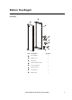
Before You Begin Inventory Item Description Quantity Fan assembly 1 Exhaust vent 1 Fan frame 1 Power cords (IEC 320) 2 5/32" hex wrench 1 M5 hex wrench 1 Cord retainer 2 Hinge screw 1 NetworkAIR Rack Air Removal Unit Installation 3
Before You Begin Tools required 5/32" hex wrench (provided) M5 hex wrench (provided) i Receiving inspection Inspect the package and contents for shipping damage, and make sure that all parts were sent. Report any damage immediately to the shipping agent, and report missing contents, damage, or other problems immediately to APC or your APC reseller.
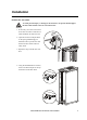
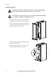
Installation Remove the rear doors To avoid personal injury or damage to the enclosure, one person should support the door while another removes it from the frame. Warning 1. If necessary, move the rack to allow for at least 30 inches of clearance to install the Rack Air Removal Unit. 2. Open the rear doors and pull down on the spring-loaded hinge pin attached to the top of the door. Lift the door from its frame and set it safely aside. 3. Repeat this step with the other rear door. 4.
Installation Install the fan frame To avoid personal injury or damage to the enclosure, one person should support the fan frame while another places the fan frame onto the enclosure. Warning Install the Rack Air Removal Unit only on racks that are loaded with equipment or are counter-weighted to avoid tipping of the rack. Warning 1. With the exhaust vent at the top of the fan frame, align the four corners of the fan frame to the four corners of the enclosure.
Installation Install the fan assembly To prevent the enclosure from tipping, all four pins must be in engaged in the enclosure frame before installing the fan assembly. Warning Warning To avoid personal injury or damage to the Rack Air Removal Unit or the enclosure, two people should support the fan assembly while another places the fan assembly onto the enclosure. 1. Align the lower pin with the hole in the hinge pin bracket on the fan frame and insert the pin into the hole. 2.
Optional Items American Power Conversion offers additional products (not included) for the Rack Air Removal Unit: • Smoke Detector Kit (ACF121) — mounting plate and smoke detector for use inside the Rack Air Removal Unit. • Air Duct Kit (ACF120) — for removal of heat from the air conditioned area.
Operation Start-up Do not remove the air intake guards. Warning Use the fan speed selector to set the fan speed based on either the wattage output of the equipment in the rack or the desired exhaust temperature. kW 5 3 2 C 6 38 35 32 OFF 29.5 Fan Speed Selector Item Description KW settings Set the fan speed according to the wattage output of the equipment in the rack. Fan speed selector Control the fan speed by wattage output or exhaust temperature.
Operation Connect the power supply 1. Set the fan speed selector to OFF. 2. Using one of the supplied power cords, connect the female end to the "A" input socket on the inside of the unit. Plug the male end into a power-protected socket. Ensure that there is adequate power for the fans to run at 100% (230V 4 A). The UPS in the rack must be sized properly to power this unit. Use the Rack Air Removal Unit only with a 3000 watt UPS or higher.
Operation To check operation of the unit: 5. Apply power to the fans by turning the fan speed selector from the OFF position to one of the four exhaust temperature settings. 6. Make sure the fans are moving. 7. Turn off the power to the unit. If no air is flowing from the Rack Air Removal Unit, check the power connection. Note How to set the fans based on wattage Determine the wattage of your equipment and set the fan speed selector to the corresponding kW setting.
Operation Temperature Override in each Fan Speed Mode kW mode Exhaust temperature mode Remote mode Temp Override Enabled Fan speed will increase when rack equipment exhaust temperature reaches 40.5° C (105° F) No Effect Depends on the fan speed selection of the remote device. Same as kW or exhaust temperature mode. In kW mode the temperature override setpoint can be set to 32.2–51.
Operation How to set the temperature override The temperature override switch is recessed inside the space marked A-Link Address. Use a small tool such as a pocket screwdriver to set the DIP switch to the correct position. Set the DIP switch labeled 1 to the desired position according to the table below.
Operation How to set the fans based on temperature A temperature probe is located in the intake vents of the Rack Air Removal Unit that measures the equipment exhaust air temperature. The unit will increase or decrease the speed of the fans to keep the equipment exhaust at the desired temperature. The appropriate fan speed is based on the equipment’s inlet air temperature and its temperature differential.
Alarm Settings The Rack Air Removal Unit has three LEDs on the front of the door that indicate whether the system is in an alarm state.
How to Communicate Using the A-Link The Rack Air Removal Unit can be used with an APC Environmental Management System that can monitor and control the unit. Connect the APC Environmental Management System any Rack Air Removal Units by using the in and out A-Link connections. How to connect to the A-Link The Rack Air Removal Unit has two connections (IN and OUT) for linking several devices together using the A-Link.
How to Communicate Using the A-Link 2. Plug the device into the A-Link “IN” connector. 3. Set the fan speed selector to the desired exhaust temperature or enclosure wattage. kW 5 3 2 6 C 38 35 32 OFF 29.5 The APC Environmental Management System will be able to monitor the temperature and the alarms on the Rack Air Removal Unit.
How to Communicate Using the A-Link To remotely control the Rack Air Removal Unit: 1. Set the second, third, and fourth DIP switches to give the Rack Air Removal Unit a unique A-Link address between one and eight, according to the chart. 1= 1 2 3 4 2= 3= 4= 5= 6= 7= 8= 1 2 3 4 1 2 3 4 1 2 3 4 1 2 3 4 1 2 3 4 1 2 3 4 1 2 3 4 1 2 3 4 2. Plug the APC Environmental Management System into the A-Link “IN” connector. 3. Set the fan speed selector to Remote.
Warranty and Service Limited warranty APC warrants the Rack Air Removal Unit to be free from defects in materials and workmanship for a period of two years from the date of purchase. Its obligation under this warranty is limited to repairing or replacing, at its own sole option, any such defective products. This warranty does not apply to equipment that has been damaged by accident, negligence, or misapplication or has been altered or modified in any way.
Life-Support Policy General policy American Power Conversion (APC) does not recommend the use of any of its products in the following situations: • In life-support applications where failure or malfunction of the APC product can be reasonably expected to cause failure of the life-support device or to affect significantly its safety or effectiveness. • In direct patient care.
Specifications — ACF102BLK 230VAC; 50Hz Electrical Power source 230VAC; 50Hz Rated current 4A Compliance VDE Physical Physical dimensions of fan assembly—h × w × d 193.55×60.78×17.78cm 76.20×23.93×7.0in Net weight—unit only 65.77kg (145lb) Shipping weight 95.27kg (210lb) Shipping dimensions 74.93×59.69×205.74cm (29.5×23.5×81in) Airflow (non ducted) 2kW 9.06 m3/min (320 CFM) 3kW 13.59 m3/min (480 CFM) 5kW 22.65 m3/min (800 CFM) 6.25kW 28.
APC Worldwide Customer Support Customer support for this or any other APC product is available at no charge in any of the following ways: • Visit the APC Web site to find answers to frequently asked questions (FAQs), to access documents in the APC Knowledge Base, and to submit customer support requests. – www.apc.com (Corporate Headquarters) Connect to localized APC Web sites for specific countries, each of which provides customer support information. – www.apc.