Service Manual Installation and Start-Up 80 kW InfraStruXure System Medium Data Centers 208/480/600 V input
About this Manual This manual is intended for APC Field Service Engineers or APC-trained installers of a 80kW InfraStruXure system. It covers basic installation and start-up. For additional information about installing the InfraStruXure system, see Certified Electrician’s Instructions (990-1469), which provides specific instructions for the electrician connecting utility to the InfraStruXure PDU.
Contents Safety ................................................................................ 1 Overview. . . . . . . . . . . . . . . . . . . . . . . . . . . . . . . . . . . . . . . . . . . . . . . . .1 Save these instructions . . . . . . . . . . . . . . . . . . . . . . . . . . . 1 Safety symbols used in this manual . . . . . . . . . . . . . . . . . . . 1 Cross-reference symbols used in this manual . . . . . . . . . . . . . 1 Warnings . . . . . . . . . . . . . . . . . . . . . . . . . . . . . . . . . .
Installation Procedures .................................................19 Level the PDU, UPS, RDP, NetShelter and Battery Enclosures . . . 19 Exchange Side Panels . . . . . . . . . . . . . . . . . . . . . . . . . . . . . . . . . . . . 20 Attach the PDU, UPS, and Battery Enclosure . . . . . . . . . . . . . . . . . 22 Ensure that All Power is Off . . . . . . . . . . . . . . . . . . . . . . . . . . . . . . . 23 Connect Utility Conductors to the PDU . . . . . . . . . . . . . . . . . . . . . .
InfraStruXure Manager Hub (or Switch) . . . . . . . . . . . . . . . . . . . . . . 46 Connect network cables to components . . . . . . . . . . . . . . . 46 Route network cables to the InfraStruXure Manager Hub (or Switch) . . . . . . . . . . . . . . . . 47 Start-Up Procedure ....................................................... 49 Safety warnings . . . . . . . . . . . . . . . . . . . . . . . . . . . . . . . 49 Ensure that all power is off . . . . . . . . . . . . . . . . . . . . . . . .
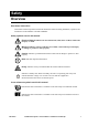
Safety Overview Save these instructions This manual contains important instructions that must be followed during installation, operation, and maintenance of the PRODUCT NAME NORMAL. Safety symbols used in this manual Electrical Hazard: Indicates an electrical hazard, which, if not avoided, could result in injury or death. Warning: Indicates a hazard, which, if not avoided, could result in personal injury or damage to product or other property.
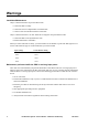
Warnings Installation/Maintenance Only a certified electrician can perform these tasks: • Connect the PDU to utility • Connect the cross tie output breaker to another PDU • Connect a switch to the EPO interface on the PDU Only a certified electrician or an APC Field Service Engineer can perform these tasks: • Connect the PDU to the Symmetra PX UPS • Perform maintenance of the PDU When you connect the PDU to utility, you must install a circuit breaker to protect the PDU against overcurrent.
SafetyWarnings Total Power Off 1. Set the Symmetra PX UPS System Enable switch to Off. 2. Set the DC Disconnect breaker of each XR Battery Enclosure to Off. 3. Set the PDU Main Input (A) switch to Off. 4. If applicable, set the PDU Bypass Input (B) switch to Off. 5. If applicable, set the PDU Cross Tie Output (X) circuit breaker to Off. 6. Set all upstream utility circuit breakers feeding the PDU to Off. 7.
SafetyWarnings EMI This equipment has been tested and found to comply with the limits for a Class A digital device, pursuant to part 15 of the FCC Rules. These limits are designed to provide reasonable protection against harmful interference when the equipment is operated in a commercial environment. This equipment generates, uses, and can radiate radio frequency energy and, if not installed and used in accordance with this user manual, may cause harmful interference to radio communications.
Site Planning Dimensions InfraStruXure PDU Shielding Partitions 4 4.7 29.5in (749.3mm) Without Shielding Trough 81.5in (2070mm) 4.72in (120mm) Wide PDU Shielding Trough With Shielding Trough 88.78in (2255mm) 7.28in (185mm) 29.5in (749.3mm) 29.5in (749.3mm) 34.5in (876.3mm) Symmetra PX UPS 23.5in (597mm) Power Module 81.5in 5.2in (130mm) (2070mm) 19in (480mm) 28in (720mm) 34.5in (876.
Site PlanningDimensions XR Battery Enclosure 23.5in (597mm) Battery Module 5.2in (130mm) 81.5in (2070mm) 28in (720mm) 19.0in (480mm) 34.5in (876.3mm) NetShelter VX Enclosure 23.5in (597mm) Shielding Partitions 23.5in (597mm) 81.5in (2070mm) 4.8in (122mm) Shielding Trough 7.2in (183mm) 23.5in (597mm) 42.2in (1071.
Site PlanningDimensions Rack Distribution Panel 81in (2060mm) 24in (610mm) 990-1467C 35in (890mm) InfraStruXure System – Service Manual – Installation and Start-Up 7
Space Considerations Study the figures below to determine your space requirements for installing the InfraStruXure PDU, Symmetra PX UPS, and XR Battery Enclosure. Consult your local codes and the NEC for additional requirements. Ceiling Clearance 18in (457.2mm) Minimum Rear Clearance Minimum Front Clearance 208V: 36in (914.4mm) 480V: 42in (1066.8mm) 208V: 36in (914.4mm) 480V: 42in (1066.
Weight Considerations Ensure that the floor and sub-floor can support the total weight of the configuration when concentrated on the leveling feet. If you are placing equipment on a raised floor, consult the flooring manufacturer for loading requirements before installing equipment.
Heat Output Consider the heat dissipation ratings of equipment to determine cooling requirements. Additional cooling equipment may be required. The following table shows the heat output of the InfraStruXure PDU and the Symmetra PX UPS. InfraStruXure PDU 208V 6,165BTU/hr. (1.81kW) 480V 5,079BTU/hr. (1.49kW) 600V 5,527BTU/hr. (1.62kW) Symmetra PX UPS 23,757BTU/hr. (6.96kW) Note: The heat output is higher while batteries are charging.
Electrical Requirements and Specifications Procedures requiring a licensed electrician Electrical Hazard: Procedures requiring a licensed electrician include: • Connection of utility conductors • Installation of a 350-, 150-, or 125-amp circuit breaker • Connection to the Main Input switch • Connection to a branch circuit • Connection to the cross tie output breaker To connect utility conductors, see Certified Electrician’s Instructions (990-1469A) included with your InfraStruXure PDU documentation.
Cross Tie Output Circuit Breaker Overview The optional cross tie output circuit breaker allows two separate UPSs that are fed from two different power sources (dual-fed) to be tied together to create a 2N system. The illustration below shows an example configuration.
Emergency Power Off (EPO) Overview To provide a mechanism for emergency power off, attach a remote switch (not included) to the EPO interface on the PDU monitoring unit. The EPO interface () is connected to the PDU Main Input switch () and to the UPS internal EPO switch (). (Control wires from the PDU to the UPS are connected during installation of the InfraStruXure system.
Basic Installation Procedure This section provides the basic steps that you need to perform when installing InfraStruXure power and rack components. Follow the references provided with each step for detailed instructions. Warning: Do not begin installing your InfraStruXure system without an APC Field Service Engineer present. 1.
Site PlanningBasic Installation Procedure 7. Connect utility conductors to the PDU. A licensed electrician must connect utility power. For instructions, see Certified Electrician’s Instructions (990-1469A) included with your InfraStruXure PDU documentation. 8. Connect AC power and control wiring. See page 26 for detailed instructions. 9. Connect DC power wiring. See page 30 for detailed instructions. 10. Connect an EPO switch to the PDU user connection plate. See page 33 for detailed instructions. 11.
Site PlanningBasic Installation Procedure 16. Start the system. Only qualified, APC-trained personnel may perform a system start-up. See page 49 for detailed instructions. 17. Configure the InfraStruXure Manager. For instructions, see the manual included with your InfraStruXure Manager.
Tools Required The following tools are required to perform the procedures in this manual. Additional tools may be required for components not covered in this manual.
Installation Procedures 18 InfraStruXure System – Service Manual – Installation and Start-Up 990-1467C
Installation Procedures Level the PDU, UPS, RDP, NetShelter and XR Battery Enclosures Leveling feet are attached under the enclosure at each corner. The leveling feet can help provide a stable base if the selected floor space is uneven, but they are not intended to compensate for a badly sloped surface. To level the enclosure: 1. Fit the 14-millimeter end of the open-ended wrench (provided) to the hex head just above the round pad on the bottom of the leveling foot.
Exchange Side Panels Before installing the InfraStruXure PDU, Symmetra PX UPS, and XR Battery Enclosure, you will need to exchange side panels so that the adjacent panels will have matching holes for joining the enclosures together and for routing input and output wiring between them.
Installation ProceduresExchange Side Panels 2. Remove the solid side panels from the sides of the UPS that will be adjacent to the PDU and the XR Battery Enclosure in your planned configuration. 3. Remove the side panels from the sides of the PDU and XR Battery Enclosure that will not be adjacent to the UPS. 4. Remove the rear hole covers from the panels that you removed in step 3. Connect Battery Enclosure communication cables: 5.
Attach the PDU, UPS, and XR Battery Enclosure 1. Move the PDU, Symmetra PX UPS, and XR Battery Enclosures into position, aligning the holes in the adjacent side panels. 2. Level the PDU, Symmetra PX UPS, and XR Battery Enclosure by using a level and adjusting the leveling feet on each enclosure. 3. Thread the chase nipple (part number: 820-0071) through the opening in the adjacent side panels of the enclosures.
Ensure that All Power is Off Electrical Hazard: Before you proceed, ensure that power is off by following the procedure in this section. Warning: Do not install any batteries into the XR Battery Enclosure or power modules into the Symmetra PX UPS until instructed to do so. How to ensure that all power is off 1. Set the UPS System Enable switch to OFF. 2. Set the XR Battery Enclosure DC Disconnect breaker to OFF.
Installation ProceduresEnsure that All Power is Off 3. Set the Main Input (A) and Bypass Input (B) switches and the Cross Tie Input (X) circuit breaker (if applicable) on the PDU to the OFF position. 4. Open (turn OFF) the Q1, Q2, and Q3 circuit breakers on the PDU. 5. Set each upstream utility circuit breaker that will feed the PDU to OFF.
Connect Utility Conductors to the PDU Warning: Only a certified electrician can connect utility conductors to the InfraStruXure PDU. For detailed instructions see Certified Electrician’s Instructions (990-1469A), which was included with your PDU documentation.
Connect AC Power and Control Wiring Note: Before you connect AC power and control wiring, connect utility conductors to the PDU. For instructions, see Certified Electrician’s Instructions included with the PDU documentation. Electrical Hazard: Only qualified personnel trained by APC may connect the AC power and control wiring. Attach AC power and control wiring to the UPS. The power wires are coiled in the bottom of the PDU.
Installation ProceduresConnect AC Power and Control Wiring Connect AC power wiring. 1. Attach the bypass wires (L1, L2, L3, N) to the four UPS bypass bus bars with corresponding labels (). 2. Attach the input wires (L1, L2, L3, N) to the four UPS input bus bars with corresponding colors and labels (). And, attach the input ground wire (G) to the ground lug to the right of the input bus bars marked . 3.
Installation ProceduresConnect AC Power and Control Wiring Connect control wiring. 4. Connect the EPO control wires from the PDU and Battery Enclosure to the EPO board on the UPS. The control wires are harnessed and coiled in the floor of the PDU and Battery Enclosure, respectively. The PDU harness connects to a 4-pin molex connector labeled J6 and the Battery Enclosure harness connects to a 4-pin molex connector labeled J8.
Installation ProceduresConnect AC Power and Control Wiring 5. Connect the Maintenance Bypass control wire harness from the PDU to the Maintenance Bypass interface board of the UPS. There are two wire harnesses coiled and secured in the PDU. One is a 6wire harness and the other is a 4-wire harness.
Connect DC Power Wiring Electrical Hazard: Only qualified personnel trained by APC may connect the XR Battery Enclosure to the Symmetra PX UPS or to another XR Battery Enclosure. Warning: The supplied power and ground wires are for internal side-panel wiring only. These wires are not for use in external conduits. Electrical Hazard: Before you begin connecting the DC power wiring, ensure that there are no battery units installed in the XR Battery Enclosures.
Installation ProceduresConnect DC Power Wiring Cascade XR Battery Enclosures If you have multiple XR Battery Enclosures as part of your InfraStruXure system, you can cascade XR Battery Enclosures to form a “daisy-chain” to a Symmetra PX UPS. Starting with the XR Battery Enclosure furthest away from the UPS: 1.
Installation ProceduresConnect DC Power Wiring Connect power cables from the XR Battery Enclosure to the Symmetra PX UPS 1. Route the XR Battery Enclosure DC output cables to the Symmetra PX UPS through the hole in the adjacent side panels. 2. Connect the XR Battery Enclosure DC output cables to the Symmetra PX UPS DC input terminal [(+) to (+), (CT) to (CT), (–) to (–)]. Warning: Text goes here.
Connect an Emergency Power Off Switch Overview Connecting the switch. Choose one of the following methods to connect a switch to the EPO interface: • Contact closure • 24 VDC • 24 VAC Note: Contact closure is recommended. The EPO connections are made at the PDU user connection plate. The figure to the right shows the location of the user connection plate. It is mounted on the roof of the PDU enclosure () and connections are made from inside the PDU.
Installation ProceduresConnect an Emergency Power Off Switch Connect an EPO switch to the user connection plate and test the switch 1. Connect the switch to the EPO connection point terminals located on the bottom side of the PDU user connection plate.
Installation ProceduresConnect an Emergency Power Off Switch 3. Test the EPO switch to ensure that it is wired and working correctly: a. Place the Arm/Test rocker switch in the Test position. The EPO state LEDs will be off and the PDU display interface will show the following alarm (in addition to any other active alarms): Active Alarm xxofxx EPO Ready To Test b. Engage the EPO switch. (If your switch is momentary, engage it with one person watching the EPO state LEDs, and another at the EPO switch.) c.
Installation ProceduresConnect an Emergency Power Off Switch Safety warnings Hazardous voltage from the branch circuit must be isolated from the 24VAC, 24VDC, and contact closure. 24VAC and 24VDC are considered Class 2 circuits as defined in Article 725 of the National Electrical Code (NFPA 70) and Section 16 of the Canadian Electrical Code (C22.1). A Class 2 circuit is a source having limited voltage and energy capacity as follows: a.
Connect User Input Contacts and Relay Outputs to the User Connection Plate Overview The figure below shows the location of the user connection plate. It is mounted on the roof of the PDU enclosure, and the connections are made from inside the enclosure. Use the knockout in the plate to route cables to and from the user connections on the plate.
Installation ProceduresConnect User Input Contacts and Relay Outputs to the User Connection Plate How to connect contacts to the PDU monitoring unit 1. Choose one or more contact numbers on the user connection plate to which you will connect the contacts. The user connection plate is connected to the PDU monitoring unit. 2. From the PDU display interface: a. Press the ESC or ENTER key to go to the top-level menu screen. b. Select Contacts on the top-level menu screen and press the ENTER key. c.
Install Shielding Troughs, Shielding Partitions, and Cable Ladders Shielding Troughs and Shielding Partitions for overhead wiring along rows If you ordered APC Shielding Troughs, Shielding Partitions, and Cable Ladders to route overhead wiring for your system, assemble the Shielding Troughs and the Shielding Partitions along the rows of enclosures and assemble the Cable Ladders between rows.
Installation ProceduresInstall Shielding Troughs, Shielding Partitions, and Cable Ladders Shielding Partitions. There are two types of Shielding Partitions, each of which forms a side wall of a trough for data cables. You can customize the width of the trough for each row of your system — wider for rows carrying many data cables, narrower for rows carrying fewer. • As the back wall, use a Shielding Partition that contains an opening for routing data cables.
Install InfraStruXure Rack-Mount Devices Install the Rack Automatic Transfer Switches (ATS) Install a Rack ATS in the top of each enclosure for overhead wiring, and in the bottom of each enclosure for wiring under the floor. See the installation instructions in the manual included with your Rack ATS. The Rack ATS is an optional component and not all InfraStruXure systems will include them.
Route and Attach Overhead Wiring Connect the sub-feed power cable conductors to a three-pole breaker on the PDU Electrical Hazard: Only licensed electricians or APC Field Service Engineers can connect the sub-feed power cable conductors to a breaker on the PDU. Ensure that the RDP breakers are OFF before beginning this procedure. The sub-feed power cable is connected to the RDP and the cable’s wires are terminated with ferrules.
Installation ProceduresRoute and Attach Overhead Wiring Route and attach power cables to equipment racks If you ordered overhead wiring, connect the prewired power cables of the InfraStruXure PDU as follows: 1. Install the Shielding Troughs, Shielding Partitions, and Cable Ladders so that you can route power cables from the PDU to the NetShelter VX Enclosures. For installation instructions, see page 39. 2. Find the numbers that indicate the enclosure to which each power cable will supply power.
Installation ProceduresRoute and Attach Overhead Wiring – For dual-feed devices within a redundant system: attach a power cable from each PDU into two different Rack PDUs in the NetShelter VX Enclosure. – For single-feed devices within a redundant system with an Automatic Transfer Switch: connect a power cable to the Automatic Transfer Switch (A and B feeds) and connect the Automatic Transfer Switch power cord to a Rack PDU in the NetShelter VX Enclosure.
Installation ProceduresRoute and Attach Overhead Wiring 5. From each NetShelter VX Enclosure, run the power cable of the appropriate APC power management device out the roof of the enclosure, through the notch in the rear side of the Shielding Trough, to the connector of the appropriate power cable from the PDU. Plug the two connectors together, and twist them clockwise to lock.
Route Data Cables to the InfraStruXure Manager Hub (or Switch) Connect network cables to components Connect a Cat-5 network cable (provided) to the network or 10Base-T ports on your APC InfraStruXure devices.
Installation ProceduresRoute Data Cables to the InfraStruXure Manager Hub (or Switch) Route network cables to the InfraStruXure Manager Hub (or Switch) Overhead routing. 1. Install Shielding Partitions and Cable Ladders. See “Install Shielding Troughs, Shielding Partitions, and Cable Ladders” on page 39. 2. Run the Cat-5 network cables (provided) from each APC device to the InfraStruXure Manager Hub (or Switch). a.
Start-Up Procedure Safety warnings This section provides instructions on how to perform a system start-up. Do not skip any steps in this procedure. Electrical Hazard: Only APC Field Service Engineers or qualified, APC-trained personnel may perform a system start-up. Warning: Do not install any batteries into the XR Battery Enclosure or power modules into the Symmetra PX UPS until instructed to do so. Ensure that all power is off 1. Set the UPS System Enable switch to OFF. 2.
Start-Up Procedure 3. Set the Main Input (A) and Bypass Input (B) switches and the Cross Tie Output (X) circuit breaker (if applicable) on the PDU to the OFF position. 4. Open (turn OFF) the Q1, Q2, and Q3 circuit breakers on the PDU. 5. Set the upstream main (and bypass, if applicable) utility circuit breaker to OFF.
Start-Up Procedure Apply power to the system 1. Set the upstream main (and bypass, if applicable) utility circuit breaker to ON. 2. Ensure A-B-C clockwise phase rotation at the top of the Main Input (A) switch on the PDU, using a phase rotation meter. 3. Set the Main Input (A) switch on the PDU to ON. 4. Verify A-B-C clockwise phase rotation at the top of the primary winding of the transformer, using a phase rotation meter. 5.
Start-Up Procedure 7. Install at least one power module in the Symmetra PX UPS. Install power modules starting from the lowest available shelf. Push each module completely into the enclosure. Heavy: Use two people to lift and install power modules. 8. Secure the power module: a. Tighten the screws on each side of the power module. b. Turn the locking latch clockwise until the arrow on the knob faces the power module. Note: The power module will not start unless the locking latch is engaged.
Start-Up Procedure 9. Set the XR Battery Enclosure DC Disconnect circuit breaker to ON. 10. Set the UPS System Enable switch to ON. When the System Enable switch is in the ON position, the UPS is running on battery. The Startup screen appears on the display interface of the Symmetra PX UPS, and then PowerView RM Rev: 000 English Please wait... the top-level status screen appears on the display interface. This may take up to 40 seconds.
Start-Up Procedure Verify UPS battery operation 1. Read the messages displayed on the Symmetra PX UPS display interface: Note any alarms and verify that they are Top-Level Status Screen appropriate for start-up conditions. |||||||||||| Fuel % ||| Load % In 208V out000V 60Hz Runtime: 1hr 2m 1. Command the UPS to apply power to the load: a. Press the ESC key to open the top-level menu. b. Select Control, and press the ENTER key. a. Select Turn Load On/Off from the Control menu, and press the ENTER key.
Start-Up Procedure The UPS interface displays the following fault screen: b. Press any key. Bypass not available Input Freq/Volt out of range Press any key... The UPS interface displays the following fault screen: c. Press the ESC key. End of Fault List Press Esc to exit or other keys to view list again The LOAD ON LED illuminates and the interface displays the following screen: UPS load is on Press any key...
Start-Up Procedure 2. Set the UPS System Enable switch to the OFF position. 3. Set the XR Battery Enclosure DC Disconnect circuit breaker to the OFF position. Verify proper voltage and phase rotation on the PDU 1. Close (turn ON) the Q1 circuit breaker on the InfraStruXure PDU to apply power to the UPS. 2. Ensure A-B-C clockwise rotation at the UPS input bus bars, using a phase rotation meter. 3.
Start-Up Procedure 6. Set the PDU Bypass Input (B) switch to ON. 7. Ensure A-B-C clockwise rotation at the UPS Bypass bus bars, using a phase rotation meter. 8. Verify proper voltage is present at the UPS Bypass bus bars (208V, metered phase-to-phase), using a true RMS voltmeter. Start the UPS 1. Set the XR Battery Enclosure DC Disconnect circuit breaker to ON. 2 . Set the UPS System Enable switch to ON.
Start-Up Procedure When the System Enable switch is in the ON position, the UPS is running on battery. The Startup screen appears on the display interface of the Symmetra PX UPS, and then PowerView RM Rev: 000 English Please wait... the top-level status screen appears on the display interface. This may take up to 40 seconds. |||||||||||| Fuel % ||| Load % In 208V out000V 60Hz Runtime: 1hr 2m 3.
Start-Up Procedure The interface will display the following fault message: a. Select Start up on Batt, and press the ENTER key. Low/No AC input Start up on Batt? Start Now The interface will display the following screen: UPS has been commanded to turn load power on... The UPS interface displays the following fault screen: b. Press any key. Bypass not available Input Freq/Volt out of range Press any key... The UPS interface displays the following fault screen: c. Press the ESC key.
Start-Up Procedure Verify proper phasing: place the UPS into bypass operation 1. Command the UPS into static bypass operation through the UPS display interface: a. Press the ESC key to open the top-level Top-Level Menu menu. Logging Control a. Select Control on the top-level menu, and Display Status Diags Setup press the ENTER key. Accessories Help Control Menu b. Select UPS Into Bypass on the Control menu, and press the ENTER key.
Start-Up Procedure 2. Close (turn ON) the Q3 circuit breaker on the InfraStruXure PDU. Note: The H2 LED above the Q2 circuit breaker illuminates, indicating that it is safe to operate the Q2 circuit breaker. 3. Open (turn OFF) the Q2 cirucit breaker on the InfraStruXure PDU. The UPS will display a Forced Bypass message on the display interface and the Fault LED will be red.
Start-Up Procedure Return from maintenance bypass operation 1. Command the UPS into static bypass operation through the UPS display interface: a. Press the ESC key to open the top-level Top-Level Menu menu. Logging Control a. Select Control on the top-level menu, and Display Status Diags Setup press the ENTER key. Accessories Help Control Menu b. Select UPS Into Bypass on the Control menu, and press the ENTER key.
Start-Up Procedure 2. Open (turn OFF) the Q3 circuit breaker on the InfraStruXure PDU. The UPS automatically returns from Static Bypass. Power the PDU Distribution Circuit Breakers 1. Ensure that the Q2 circuit breaker on the PDU is closed (ON). Note: When Q2 is closed, the PDU distribution panel is energized. 2. Close (turn ON) the PDU distribution panel circuit breakers. Note: When the distribution panel circuit breakers are closed, the PDU power cables and connected equipment are energized.
Start-Up Procedure Close Cross-Tie 1. If applicable, ensure A-B-C clockwise rotation at the bottom of the PDU cross tie output circuit breaker, using a phase rotation meter. 2. If applicable, verify that there is NO voltage present across the PDU cross tie circuit breaker, and that proper voltage is present on each side of the circuit breaker (208V, metered phase-to-phase), using a true RMS voltmeter. Warning: There should be no voltage present across the Cross Tie Output circuit breaker. 3.
Configure the InfraStruXure Manager Once all equipment is installed, the network cables are connected to the InfraStruXure Manager hub (or switch), and start-up of the system is complete, configure the InfraStruXure Manager. For instructions, see the InfraStruXure Manager Installation and Quick-Start manual included with your InfraStruXure Manager.
Appendix A : System Operation How to Transfer the PRODUCT NAME NORMAL into Maintenance Bypass Operation Note: Select Help from the top-level menu screen of the PDU display interface and select the first help topic, Putting the PDU into Maintenance Bypass, or follow the procedure below. When servicing the PRODUCT NAME NORMAL, transfer the PRODUCT NAME NORMAL into maintenance bypass operation.
Appendix A : System OperationHow to Transfer the PRODUCT NAME NORMAL into Maintenance Bypass Operation Note: The H3 LED above the Q3 circuit breaker illuminates, indicating that it is safe to operate the Q3 circuit breaker. 2. Close (turn ON) the Q3 circuit breaker on the PDU. If you have a dual-fed system, check to ensure that power is available before operating the Q3 circuit breaker.
Appendix A : System OperationHow to Transfer the PRODUCT NAME NORMAL into Maintenance Bypass Operation 5. Set the Battery Enclosure DC Disconnect circuit breaker to the OFF position. 6. Open (turn OFF) the Q1 circuit breaker on the PDU. 7. If applicable, set the PDU Q10 Bypass Input (B) switch to OFF. The UPS is now in maintenance bypass operation.
How to Return from Maintenance Bypass Operation Note: Select Help from the top-level menu screen on the PDU display interface and select the second help topic, Returning from PDU Maintenance Bypass, or follow the procedure below: 1. Close (turn ON) the Q1 circuit breaker on the PDU. 2. If applicable, set the PDU Q10 Bypass Input (B) switch to ON. 3. Set the XR Battery Enclosure DC Disconnect circuit breaker to ON. 4. Set the UPS System Enable switch to the ON position.
Appendix A : System OperationHow to Return from Maintenance Bypass Operation 5. Command the UPS to apply power to the load: a. Press the ESC key at the top-level status screen to open the top-level menu and have access to eight submenus. b. Select Control, and press the ENTER key. Top-Level Menu Control Status Setup Accessories Logging Display Diags Help Control Menu c. Select Turn Load On from the Control menu, and press the ENTER key.
Appendix A : System OperationHow to Return from Maintenance Bypass Operation Control Menu c. Select UPS Into Bypass on the Control menu, and press the ENTER key. UPS Into Bypass Do Self Test Simulate Power Fail Graceful Reboot Graceful Turn Off Start Runtime Cal Turn Load On Confirmation Screen d. Confirm the selection on the next screen: select Yes, UPS into Bypass, and press the ENTER key.
How to Ensure Total Power Off 1. Command the UPS to turn off power to the load: a. Press the ESC key at the top-level status screen to open the top-level menu and have access to eight submenus. b. Select Control, and press the ENTER key. Top-Level Menu Control Status Setup Accessories Logging Display Diags Help Control Menu c. Select Turn Load Off from the Control menu, and press the ENTER key.
Appendix A : System OperationHow to Ensure Total Power Off 3. Set the Battery Enclosure DC Disconnect circuit breaker to the OFF position. 4. Pull out all battery units in the Battery Enclosures to the red battery disconnect line. 5. Set the Main Input breaker (or switch) (A), and, if applicable, the Q10 Bypass Input switch (B), and Cross Tie Output circuit breaker (X) on the PDU to the OFF position. 6. Open (turn OFF) the Q1, Q2, and Q3 circuit breakers on the PDU. 7.
How to Apply Power to the System This procedure instructs on how to apply power to a system that has already been installed. For initial start-up instructions, see InfraStruXure 80kW Installation and Start-Up. 1. Set the upstream utility, and, if applicable, the bypass input and cross tie utility circuit breaker to ON. A B X 1. Set the Main Input (A) breaker (or switch) on the PDU to ON. 2. Close (turn ON) the Q1 circuit breaker on the PDU to apply power to the UPS. 3.
Appendix A : System OperationHow to Apply Power to the System 4. Ensure that all battery units are pushed all the way into the Battery Enclosures and locked into position. 5. Set the Battery Enclosure DC Disconnect circuit breaker to ON. 6. Set the UPS System Enable switch to ON When the System Enable switch is placed in the ON position, the Startup screen appears on the display interface of the Symmetra PX UPS. PowerView RM Rev: 000 English Please wait...
Appendix A : System OperationHow to Apply Power to the System 7. Read the messages displayed on the UPS display interface: a. Note any alarms, and verify that they are appropriate for start-up conditions. b. Verify that the UPS accepts the input. Top-Level Status Screen |||||||||||| Fuel% ||| Load% In 208V out000V 60Hz Runtime: 1hr 2m 8. Command the UPS to apply power to the load: a. Press the ESC key at the top-level status screen to open the top-level menu and have access to eight submenus. b.
Appendix A : System OperationHow to Apply Power to the System 9. To apply power to the PDU distribution panel, close (turn ON) the Q2 circuit breaker on the PDU. 10. To apply power to the PDU power cords and connected equipment, close (turn ON) the distribution panel circuit breakers. 11. If applicable, close (turn ON) the Cross Tie Output (X) circuit breaker.
2/0 0W1870 Q3 0W1860 320A 4P 80A 2A 80A 80A 80A Bottom Feed Option 600V: 0W1782 480V: 0W1782 208V: 0W1783 600V 480V 208V 500 MCM AC Mains GND S1 112.
H3 2/0 Q3 0W1860 320A 4P 2A s 80A Dual Feed Option 80A 80A V 500 MCM Bypass Input Bottom Feed Option 208V 500 MCM } Bottom Feed 0W1884 Option 208V S1 400A 3P S 80A 208V Bypass 0W1879 A } 0W1785 AC Input F1 160A 3P S2 400A 3P V Output FL=121A 208V 0W1811 A 2A 0W1864 0W1901 GEC GND AC Input GND 400A 3P Bypass Input GND X-Tie GND Output 2/0 Q1 360A 3P V H2 0W1867 0W1869 Symmetra PX 80kW V 0W1874 2A 0W1862 Mains Input 320A 4P Q2 0W1873 InfraStruXure System – Service
990-1467C 80kW PDU with System Bypass 208V Input, Single-feed, without a Transformer 2/0 Q3 0W1860 320A 4P 80A 2A 80A 80A 80A 0W1879 } 0W1884 208V 500 MCM AC Mains GND V 0W1867 V S A Bypass Output FL=121A Q1 360A 3P 2A 2/0 0W1864 Mains Input Symmetra PX 80kW 0W1862 0W1873 Bottom Feed Option Fx 350A Q2 320A 4P 2A 20A 20A V 0W1874 I 20A 2/0 20A I I I I I I I I I I 42-Position 400-Amp Rated Panel Load Port Option This drawing and specifications herein are the property of Americ
Appendix C: Changes in This Manual Overview The following list documents the specific changes made to this manual since its last release (9901467A). General changes An index was added to the end of this manual. See pages 85–87. Changes by page number Pages 33–36 Updated instructions on how to connect an Emergency Power Off (EPO) switch to the user connection plate. Pages 37–38 Updated instructions on how to connect user contacts and added information about connecting relay outputs.
Index B D battery enclosure attaching the, 22 cascading, 31 connect communication cables, 21 connect DC power wiring, 30– 32 dimensions, 6 level the, 19 space considerations, 8 weight considerations, 9 bypass input switch, 24, 50, 69, 70, 74, 75 electrical requirements, 11 bypass operation place the UPS into, 60–61 returning from, 62–63, 70–72 transferring into, 67–69 DC disconnect circuit breaker, 23, 57, 69, 70, 74, 76 diagrams, single-line, 79–?? C cable ladders, installing, 40 cables connect battery
mount devices, 41 install shielding troughs, shielding partitions, and cable ladders, 39–40 level the PDU, UPS, RDP, NetShelter, and battery enclosures, 19 route and attach overhead wiring, 42–45 total power off, ensuring, 23–24 the UPS into, 67–69 system, applying power to, 75– 78 total power off, ensuring, 73–74 P PDU. See InfraStruXure PDU.
T W tools, required for installation, 17 total power off ensuring, 23–24, 49, 73–74 overview, 3 warnings, 2–4 electric shock risk, 3 Emergency Power Off (EPO), 3 for installation, 14 installation/maintenance, 2 performing maintenance while the PDU is receiving input power, 2 wiring connect AC power and control, 26–29 connect DC power, 30–??, 30– 32 overhead, route and attach, 42– 45 recommended sizing, 11 torque according to size, 11 U UPS attaching the, 22 bypass operation, placing, 60– 61 bypass opera
APC Worldwide Customer Support Customer support for this or any other APC product is available at no charge in any of the following ways: • Visit the APC Web site to access documents in the APC Knowledge Base and to submit customer support requests. – www.apc.com (Corporate Headquarters) Connect to localized APC Web sites for specific countries, each of which provides customer support information. – www.apc.com/support/ Global support searching APC Knowledge Base and using e-support.