Operation Modular Power Distribution Unit PDPM138H-5U PDPM138H-R PDPM72F-5U PDPM72F-R PDPM277H PDPM144F
About this Manual This manual is intended for users of the Modular Power Distribution Unit (PDU). It refers to important safety warnings and instructions, gives an introduction to the display interface, and provides information on operation, troubleshooting, and maintenance.
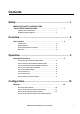
Contents Safety ............................................................................... 1 IMPORTANT SAFETY INSTRUCTIONS - SAVE THESE INSTRUCTIONS . . . . . . . . . . . . . . . . . . . . . . . . . . . . . . 1 Symbols used in this manual . . . . . . . . . . . . . . . . . . . . . . . . 1 Regulatory Agency Approval . . . . . . . . . . . . . . . . . . . . . . . . 1 Overview .......................................................................... 2 User Interface . . . . . . . . . . . . . . . . . . . .
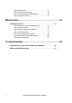
Modules in the system . . . . . . . . . . . . . . . . . . . . . . . . . . . .13 How to change the display settings . . . . . . . . . . . . . . . . . . .14 How to set and change the password settings . . . . . . . . . . . .14 How to change date and time . . . . . . . . . . . . . . . . . . . . . . .15 Maintenance ................................................................... 16 Parts Replacement . . . . . . . . . . . . . . . . . . . . . . . . . . . . . . . . . . . . . . .
Safety IMPORTANT SAFETY INSTRUCTIONS - SAVE THESE INSTRUCTIONS This manual contains important instructions that must be followed during installation, operation, and maintenance of the Modular Power Distribution Unit (PDU). For safety reasons, only trained users are allowed to operate the display and replace the Power Distribution Modules: The Power Distribution Modules are hot-swappable, and may be replaced while the unit is operating.
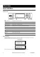
Overview User Interface Interface area Normal ESC Check Log ? Warning Critical Normal LED When green, no alarms are present. Check Log LED When green, a new event has been added to the log. Warning LED When yellow, a warning alarm exists. CriticaL LED When red, there are one or more critical alarms in the system. LCD SCREEN Displays alarms, status data, instructional help, and configuration items. UP and DOWN keys Scrolls through menu items.
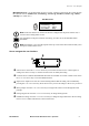
Overview: User Interface Main Menu Screen. Use the Main Menu Screen to operate, configure, and monitor the system through the sub menu screens: Module View, Load/Energy, Circuit Cfg, Volt Meter, Alarms, Log, Admin, and Help (see "Menu tree"). Main Menu Screen Module View Load/Energy Circuit Cfg Volt Meter Alarms Log Admin Help Note: If the user interface is inactive for the time configured for the password time-out, it returns to the scrolling status screens.
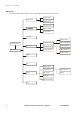
Overview: User Interface Menu tree The menu tree provides a quick overview of the functions and views you can access.
Operation Operation Procedures How to perform a total power off procedure Caution: This procedure will cut the supply to the load. Set all circuit breakers of the Power Distribution Module to OFF. Set all utility/mains circuit breakers to OFF.
Operation: Operation Procedures How to view the Power Distribution Module status The Module View Screens are used for status information on a Power Distribution Module level. Select Module View on the Main Menu Screen and press ENTER. Press ENTER at the Module number and scroll through the list of modules to the specific module and One-corded press ENTER. To view more information about the module, select Circuit Details and press ENTER.
Operation: Operation Procedures How to view Power Distribution Module information Select Module View on the Main Menu Screen and press ENTER. Module View Load/Energy Circuit Cfg Volt Meter Module:>xx Status: Critical >Circuit Details >About This Module Alarms Log Admin Help Press ENTER at the Module number and scroll through the list of modules to the specific module and press ENTER. Select About This Module and press ENTER.
Operation: Operation Procedures How to view circuit status information The Load/Energy screens are used for status information on a circuit level and the data is grouped by output cable. Scroll to the list to go to the specific circuit. The circuit names are stated for identification. Refer to "How to set the name and location of the circuits" for information on how to set the circuit name. Select Load/Energy on the Main Menu Screen and press ENTER.
Operation: Operation Procedures How to view the log The log saves information and a message every time a change in the PDU is detected. Alarms and events are recorded in the log and displayed as an active alarm. Status changes are only displayed in the log, and will not display as an active alarm. Note: Viewing the log will clear the Check Log LED. Select Log on the Main Menu Screen, and press Module View Load/Energy Circuit Cfg Volt Meter >New Logged Items >Entire Log >Clear Log ENTER.
Configuration Settings How to set up the network Select Admin on the Main Menu Screen, and press ENTER. Select Network Setup and press ENTER. Set the IP-address and subnet mask for the system. Press the continue arrow and set the gateway and MAC address. 10 Module View Load/Energy Circuit Cfg Volt Meter >Network Setup >Local Interface >Date & Time >Device ID >Mode: Fixed IP Addr IP:xxx.xxx.xxx.xxx SM:xxx.xxx.xxx.xxx GW:xxx.xxx.xxx.
Configuration: Settings How to set the name and location of the circuits Select Circuit Cfg on the Main Menu Screen, and press ENTER. Select Individual Load Cfg and press ENTER. Select Name/Location and press ENTER. Change the settings for circuit name and circuit location. Use the UP and DOWN arrow keys to select a character and press ENTER to confirm and go to the next character.
Configuration: Settings How to set the individual alarm thresholds The Individual Load Cfg screens are used to set the alarm thresholds for a single Power Distribution Module in the system. It is also possible to set the settings for all modules at the same time. Refer to "How to set the alarm thresholds for all Power Distribution Modules in the system". Select Circuit Cfg on the Main Menu Screen, and press ENTER. Select Individual Load Cfg and press ENTER.
Configuration: Settings How to set the alarm thresholds for all Power Distribution Modules in the system The Mass Configuration screens are used to set the alarm thresholds for all Power Distribution Modules in the system. Select Circuit Cfg on the Main Menu Screen, and press ENTER. Module View Load/Energy Circuit Cfg Volt Meter Alarms Log Admin Help Select Mass Configuration and press ENTER.
Configuration: Settings How to change the display settings Select Admin on the Main Menu screen and press ENTER. Select Local Interface and press ENTER. Select Display Behavior and press ENTER. From this screen the settings for contrast, key click, beeper volume and check log light can be changed.
Configuration: Settings How to change date and time Select Admin on the Main Menu screen and press ENTER. Select Date & Time and press ENTER. From this screen the date format, date, and time can be changed.
Maintenance Parts Replacement How to determine if you need a replacement part To determine if you need a replacement part, contact APC Customer Support and follow the procedure below so that the APC Customer Support representative can assist you promptly: 1. In the event of a module failure, the display interface may show additional “fault list” screens. Press any key to scroll through these fault lists, record the information, and provide it to the representative. 2.
Maintenance: Parts Replacement How to install a Power Distribution Module Electrical Hazard: To prevent arcing when removing an APC Power Distribution Module (PDM) from the Modular Power Distribution Unit (PDU), set all PDMs to OFF. Do not remove the modules when they are under load. Caution: PDMs must be replaced by trained personnel only (see the section "Safety"). Note: The PDM can be safely installed into a powered rack.
Maintenance: Parts Replacement How to remove a filler plate Note: Filler plates come pre-installed in UL certified Modular Power Distribution Unit (PDU) products PDPM72F-5U and PDPM72F-R when a Power Distribution Module (PDM) is not installed. Note: Do not throw away the filler plate. Keep it for potential later use. Press down on the clip to remove the filler plate. Pull out the plate from the unit =Verify that all breakers are in the OFF position.
Maintenance: Parts Replacement Vertical Rack Distribution Panel Horizontal Rack Distribution Panel Slide the PDM all the way into the slots. Close the latch to secure the module in the busbar. Use plastic ties to secure loose cable(s) to the enclosure (only in Vertical Rack Distribution Panels). Connect the PDM cable to the load. Turn the PDM circuit breakers ON (see the drawing under “How to install a Power Distribution Module” on page 17).
Maintenance: Parts Replacement How to test the Residual Current Device Note: Pushing the test button will open circuit breakers distributing power to the equipment. Press the test button and confirm that the Residual Current Device (RCD) and adjacent circuit breaker trip to the OFF position. Reset the RCD and circuit breaker into normal by pushing the toggle to the ON position.
Maintenance: Parts Replacement How to reinstall a filler plate Position the filler plate in front of the open PDM location. Insert the bottom tab of the filler plate into the slot. Tilt up the filler plate and snap it into position until it is secured.
Troubleshooting LED Indication on the Power Distribution Modules There are three LEDs on each Power Distribution Module. The LEDs indicate the following conditions: • Red: A critical alarm. LED Indication • Yellow: A warning alarm • Green: No alarm. • Flashing green: The module is being identified by the system.
Status and Alarm Messages This section lists the status and alarm messages that the PDU might display. The messages are listed in alphabetical order, and a suggested corrective action is listed with each alarm message to help you troubleshoot problems. Display Message Detailed Description Corrective Action High Module Current. The high module current threshold has been exceeded. Evaluate the threshold setting. If necessary, adjust it for your situation. High Subfeed Current.
APC Worldwide Customer Support Customer support for this or any other APC product is available at no charge in any of the following ways: • Visit the APC Web site to access documents in the APC Knowledge Base and to submit customer support requests. – www.apc.com (Corporate Headquarters) Connect to localized APC Web sites for specific countries, each of which provides customer support information. – www.apc.com/support/ Global support searching APC Knowledge Base and using e-support.