5 PM3 and PM4 Series Modular Surge Protection Device (SPD) User’s Manual Copyright © 2000 American Power Conversion Corporation 132 Fairgrounds Road P.O.
6XUJH$UUHVW 30 6HULHV Contents INTRODUCTION.......................................................................................................................................... 1 Installation.......................................................................................................................................... 1 Testing ................................................................................................................................................
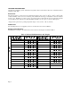
Contents - continued Tables Table 1 - PM3 and PM4 Dimensions and Weights ............................................................................ 2 Table 2 - Voltage Rating and Service Type (by Model) ..................................................................... 4 Table 3 - Relay Contact Pin Arrangement ....................................................................................... 11 Table 4 - Replacement Parts List........................................................................
INTRODUCTION Thank you for choosing the APC SurgeArrest PM3 or PM4 Series Surge Protection Device. The APC modular Surge Protection Device (SPD) is a high quality, high energy surge attenuation system that has been designed to protect sensitive equipment from damaging transient voltage surges. Proper installation is imperative to maximize the surge suppressor’s effectiveness and performance. Read and understand all information contained in this manual prior to installation.
LOCATION CONSIDERATIONS 7KH IROORZLQJ SDUDJUDSKV SURYLGH LQIRUPDWLRQ DQG JXLGDQFH DERXW ZKDW VKRXOG EH WDNHQ LQWR FRQVLGHUDWLRQ EHIRUH LQVWDOOLQJ DQ $3& 63' Environment The unit is designed to operate indoors in an ambient temperature* range of -40o C (-40o F) to +60o C (+140o F) with a relative humidity of 0% to 95% non-condensing. The standard unit is in a Type 1 industrial use enclosure intended for indoor use. Primarily, it provides a degree of protection against contact with the enclosed equipment.
Service Clearance In addition to national and local code requirements, 32 inches of service clearance is needed at the front of the SPD.
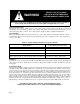
:$51,1* 9(5,)< 7+$7 $// 32:(5 &,5&8,76 $5( '( (1(5*,=(' %()25( 0$.,1* &211(&7,216 All electrical connections should be performed by a qualified (licensed) electrician. All wiring must comply with the National Electric Code (NEC) and applicable local codes. Overcurrent Protection The Surge Protection Device (SPD) draws very little current under normal conditions and will only conduct for a brief duration upon encountering a transient surge voltage.
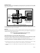
Parallel Connection When making a parallel type of connection (Figure 1), the length of the wiring to the Surge Protection Device (SPD) must be kept as short as possible to substantially enhance the performance. Long wire runs are to be avoided if the unit is to perform as intended.
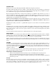
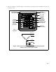
3. Open the door on the unit by loosening the two screws that secure the door latches in place. Slide the top latch upward and rotate it so that it no longer secures the door. Slide the bottom latch downward and rotate it so that it no longer secures the door. 4. Drill a hole large enough to allow for the installation of the correct sized UL approved conduit with anti-short bushings (not supplied) to accomodate the wiring being installed.
8. Use an AC voltmeter to check all voltages to ensure that the proper unit type has been installed for the service rating being protected. 0RXQWLQJ +ROH SODFHV 0RXQWLQJ )ODQJH SODFHV 'RRU /DWFK SODFHV 1(875 $/ *URXQG &RQQHFWRU 3KDVH $ 3KDVH % 3KDVH & &RQQHFWRUV 1HXWUDO &RQQHFWRU 6XUJH 0RGXOH ZLWKRXW /(' *5281 ' 6XUJH 0RGXOH ZLWK /(' SODFHV 3+$6( $ 3+$6( % 5HWDLQLQJ 6FUHZ SODFHV 3+$6( & )XVH SODFHV Not to exact scale. Door remove for clarity.
Disconnect Switch Option All APC modular series SPDs can be equipped with an optional internal disconnect switch (Figure 3). The disconnect switch provides a means to de-energize the entire suppressor, to facilitate servicing of unit’s components. (See Warning regarding the Neutral when testing the distribution system). NOTE: A disconnect switch will add length, which increases the response time and the clamp voltage.
:$51,1* 0$,17(1$1&( 2) 7+,6 685*( 3527(&7,9( '(9,&( 6+28/' %( 3(5)250(' %< 48$/,),(' 3(56211(/ 21/< '85,1* 1250$/ 23(5$7,21 +$=$5'286 92/7$*(6 $5( 35(6(17 ,16,'( 7+( 81,7 :+(1 6(59,&,1* 7+,6 81,7 %( 685( 72 )2//2: $// (/(&75,&$/ 6$)(7< 35(&$8 7,216 $// 32:(5 6285&(6 72 7+,6 81,7 6+28/' %( /2&.(' 2)) %()25( 6(59,&,1* 7+,6 :,// 35(9(17 7+( 5,6. 2) 5(&(,9,1* $1 (/(&75,&$/ 6+2&. Operation and Features SPD’s do not require alot of operator intervention after installation.
Status Panel Controls, Indicators, and Alarms $OO LQGLFDWRUV DQG FRQWUROV DUH ORFDWHG RQ WKH IURQW GLDJQRVWLF SDQHO )LJXUH RI WKH 6'3 XQLW (DFK SKDVH IHDWXUHV D WUL FRORU /(' LQGLFDWRU *UHHQ LQGLFDWHV FRUUHFW RSHUDWLRQ $PEHU LQGLFDWHV UHGXFHG SURWHFWLRQ 5HG LQGLFDWHV ORVV RI SURWHFWLRQ ,I DQ LQRSHUDWLYH FRQGLWLRQ ZHUH WR RFFXU WKH EXLOW LQ DXGLEOH DODUP ZLOO VRXQG DQG WKH UHG 6HUYLFH /(' ZLOO LOOXPLQDWH 7KLV LQGLFDWHV WKDW WKH XQLW QHHGV HYDOXDWLRQ E\ D TXDOLILHG HOHFWULFLDQ RU WHFKQLFLDQ 8QWL
Dry Contacts Option The Dry Contacts option utilize a DB-9 connector. This feature provides two sets of both normally open (NO) and normally closed (NC) contacts through the DB-9 connector. These relay contacts can be used for remote indication of the SPD’s operating status by changing state when there is an alarm condition. Examples could include a computer interface board, an emergency management system, etc. The relay contact pin arrangement is defined in Table 3. (Please note the jumpered connections.
$ODUP $XGLEOH 9LVXDO 5HG 6HUYLFH /(' /LW" 67$57 1R
:$51,1* 0$,17(1$1&( 2) 7+,6 685*( 3527(&7,9( '(9,&( 6+28/' %( 3(5)250(' %< 48$/,),(' 3(56211(/ 21/< '85,1* 1250$/ 23(5$7,21 +$=$5'286 92/7$*(6 $5( 35(6(17 ,16,'( 7+( 81,7 :+(1 6(59,&,1* 7+,6 81,7 %( 685( 72 )2//2: $// (/(&75,&$/ 6$)(7< 35(&$8 7,216 $// 32:(5 6285&(6 72 7+,6 81,7 6+28/' %( /2&.(' 2)) %()25( 6(59,&,1* 7+,6 :,// 35(9(17 7+( 5,6. 2) 5(&(,9,1* $1 (/(&75,&$/ 6+2&.
Diagnostic Board Removal and Replacement Instructions To remove and replace the Diagnostic Board, refer to Figure 7 and proceed as follows: 1. Disconnect power to the SPD. 2. Remove the board from the standoffs. 3. Remove the connectors one at a time from the existing board and insert them into the appropriate connector on the replacement board. 4. Install the replacement board onto the standoffs.
$OLJQ WKH UHSODFPHQW VXUJH PRGXOH ZLWK WKH PRXQWLQJ KROHV LQ WKH FKDVVLV ,QVWDOO WKH WZR DOOHQ KHDG VFUHZV UHPRYHG LQ VWHS DQG WRUTXH WR LQFK SRXQGV 3RZHU XS WKH 63' DQG YHULI\ WKDW WKH JUHHQ /(' LV OLW DQG WKDW DOO DODUPV KDYH FOHDUHG /(' ,QGLFDWRU $OOHQ +HDG 6FUHZ SODFHV 6XUJH 0RGXOH ,QVXODWRU 3DQHO %DFNSODQH $OOHQ +HDG 6FUHZ SODFHV )LJXUH 6XUJH 0RGXOH 5HPRYDO DQG 5HSODFHPHQW Preventive Maintenance - Inspection and Cleaning Inspection of the SPD should be performed peri
Replacement Parts Listing APC offers the items listed in Table 4 as field replaceable items.
Limited Warranty APC warrants it’s AC panel protection products against defects in workmanship and materials for 5 years from the date of original purchase. The panel protection device must be installed by a qualified and licensed electrician in order to qualify for warranty proctection. Liability is limited to the replacement of the defective product. A Return Material Authorization must be given by APC prior to the return of any product (see Technical Support and Customer Service).