Installation and Operation Manual APC 2X Series Hardwire Products PMP2X-A PMF2X-A PMG2X-A PMH2X-A
APC hardwired products are designed to provide specification-grade performance at the service entrance, branch panels, or other critical locations for today’s electrical distribution systems. APC Hardwire Panel Mount Products package multi-phase surge suppression and noise suppression into a compact, economical NEMA 4x enclosure. The units come standard with an audible alarm, dry contacts, and status indicator LEDs. Compliant with UL1449 3rd Edition requirements dated September 29, 2009.
Table of Contents Precautions ............................................................................................... 4 Introduction ............................................................................................... 6 Unpacking and Preliminary Inspection ................................................... 7 Storage ....................................................................................................... 7 Identification Nameplate ...........................................
Precautions Precautions DANGER HAZARD OF ELECTRIC SHOCK, EXPLOSION, OR ARC FLASH • Apply appropriate personal protective equipment (PPE) and follow safe electrical work practices. See NFPA 70E. • This equipment must only be installed and serviced by qualified electrical personnel. • Turn off all power supplying this equipment before working on or inside equipment. • Always use a properly rated voltage sensing device to confirm power is off.
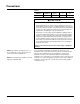
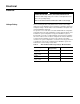
Precautions Table 1: SPD Device Per Phase I2t Iapparent Ip Ith PM2X Series 44 kA2 seconds 8,500 A RMS 20,000 A RMS 110 A CAUTION LOSS OF SURGE SUPPRESSION • During installation into an electrical system, SPDs must not be energized until the electrical system is completely installed, inspected, and tested. All conductors must be connected and functional, including the neutral. The voltage rating of the device and system must always be verified before energizing the surge protective device.
Introduction Introduction Thank you for choosing the APC SurgeArrest® PM_2X Series Hardwire Surge Protection Device. The APC Hardwired Surge Protection Device (SPD) is a high-quality, high-energy surge attenuation system that has been designed to protect sensitive equipment from damaging transient voltage surges. Proper installation is imperative to maximize the surge suppressor’s effectiveness and performance. This manual is to be used as a guide for installing the device.
Inspection Unpacking and Preliminary Inspection Inspect the entire shipping container for damage or signs of mishandling before unpacking the device. Remove the packing material and further inspect the device for any obvious shipping damage. If any damage is found and is a result of shipping or handling, immediately file a claim with the shipping company. Storage The device should be stored in a clean, dry environment. Storage temperature is -40 °F to +149 °F (-40 °C to +65 °C).
Electrical Electrical DANGER HAZARD OF ELECTRIC SHOCK, EXPLOSION, OR ARC FLASH Confirm the SPD voltage rating on the module or nameplate label is the same as the operating voltage. Failure to follow these instructions will result in death or serious injury. Voltage Rating Prior to mounting the SPD, verify that the device has the same voltage rating as the power distribution system in which it is installed.
Electrical Wire Leads Twenty-four inch leads are provided. The wire leads are 10 AWG stranded copper wire. See Table 3 for wire color.
Electrical Location of Surge Protective Device (SPD) Install SPDs on the load side of the main overcurrent protection to comply with NEC® Article 285 for Type 2 SPD. Locate the SPD as close as possible to the circuit being addressed to minimize the wire length and optimize SPD performance. Avoid long wire runs so that the device will perform as intended.
Grounding System Grounding CAUTION LOSS OF SURGE PROTECTION • Must be installed on solidly grounded power systems. Do not use on ungrounded systems. • Verify that the service entrance equipment is bonded to ground in accordance with all applicable codes. • Verify that the neutral terminals are grounded to system ground in accordance with all applicable codes. Failure to follow these instructions can result in equipment damage.
Installation Installation DANGER HAZARD OF ELECTRIC SHOCK, EXPLOSION, OR ARC FLASH • Apply appropriate personal protective equipment (PPE) and follow safe electrical work practices. See NFPA 70E. • This equipment must only be installed and serviced by qualified electrical personnel. • Turn off all power supplying this equipment before working on or inside equipment. • Always use a properly rated voltage sensing device to confirm power is off.
Wiring Wiring DANGER HAZARD OF ELECTRIC SHOCK, EXPLOSION, OR ARC FLASH • Apply appropriate personal protective equipment (PPE) and follow safe electrical work practices. See NFPA 70E. • This equipment must only be installed and serviced by qualified electrical personnel. • Turn off all power supplying this equipment before working on or inside equipment. • Always use a properly rated voltage sensing device to confirm power is off.
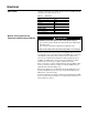
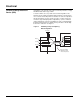
Wiring PM2X Series Wiring Diagrams Figure 3: Mounting Unit Figure 4: Single-Phase, 3-Wire, Grounded Installation Figure 5: Three-Phase, 3- or 4-Wire, Grounded Wye Installation Lock Nut 0.75 in. [19 mm] knockout (trade size) Actual hole size 1.0 in. [25 mm] NOTE: The neutral conductor is not present on 3-wire, grounded neutral power systems. For proper operation of diagnostics, the neutral (white) conductor of the SPD must be connected to ground.
Operation Operation DANGER HAZARD OF ELECTRIC SHOCK, EXPLOSION, OR ARC FLASH • Apply appropriate personal protective equipment (PPE) and follow safe electrical work practices. See NFPA 70E. • This equipment must only be installed and serviced by qualified electrical personnel. • Turn off all power supplying this equipment before working on or inside equipment. • Always use a properly rated voltage sensing device to confirm power is off.
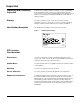
Operation Dry Contacts The PM2X series SPD device is provided with dry contacts. The connection for the dry contacts is provided by 24-inch wire leads. The wire leads are 22 AWG stranded copper wire. See Table 5 for wire color and contact state. The unpowered state shall be closed between the red wire (common) and the yellow wire (normally closed). This is also the alarm condition.
Operation Remote Monitor Option The option has two LEDs, one red and one green, and an audible alarm with an enable/disable switch. Normal status is a lit green LED, and no audible alarm. To test the integrity of the remote monitor, press the push-to-test switch. The green LED will turn off, the red LED will turn on, and the alarm will sound, if the alarm is enabled. Releasing the switch will complete the test; the red LED will turn off, the green LED will turn on and the alarm will shut off.
Maintenance Preventive Maintenance DANGER HAZARD OF ELECTRIC SHOCK, EXPLOSION, OR ARC FLASH • Apply appropriate personal protective equipment (PPE) and follow safe electrical work practices. See NFPA 70E. • This equipment must only be installed and serviced by qualified electrical personnel. • Turn off all power supplying this equipment before working on or inside equipment. • Always use a properly rated voltage sensing device to confirm power is off.
Installation and Operation Manual 19
APC Worldwide Customer Support Customer support for this or other APC products is available at no charge in the following ways: • Visit the APC website to access documents in the APC Knowledge Base and to submit customer support requests. — www.apc.com (Corporate Headquarters) Connect to localized APC Web sites for specific countries, each of which provides customer support information. — www.apc.com/support Global support searching APC Knowledge Base and using e-support.