Installation and Operation Manual APC Panel Mount Modular SPDs PMP3S-A PMP3DS-A PMP4S-A PMP4DS-A PMF3S-A PMF3DS-A PMF4S-A PMF4DS-A PMG3S-A PMG3DS-A PMG4S-A PMG4DS-A PML3S-A PML3DS-A PML4S-A PML4DS-A
The APC Modular Panel Product Surge Protective Devices (SPD), are designed to provide specification grade performance at the service entrance, branch panels or other critical locations. The APC SurgeArrest® Modular Panel Mount Products have replaceable phase modules with integrated LED monitoring, a display panel with surge counter and LED status indicators, an audible alarm, and comes in a NEMA 3R/12 Enclosure.
Table of Contents Precautions ............................................................................................... 4 Introduction ............................................................................................... 6 Unpacking and Preliminary Inspection ........................................................ 7 Storage ....................................................................................................... 7 Safety Labels .................................................
Precautions Precautions DANGER HAZARD OF ELECTRIC SHOCK, EXPLOSION, OR ARC FLASH • Apply appropriate personal protective equipment (PPE) and follow safe electrical work practices. See NFPA 70E. • This equipment must only be installed and serviced by qualified electrical personnel. • Turn off all power supplying this equipment before working on or inside equipment. • Always use a properly rated voltage sensing device to confirm power is off.
Precautions CAUTION LOSS OF SURGE SUPPRESSION • Do not energize the SPDs until the electrical system is completely installed, inspected, tested, and all conductors have been connected and functional, including the neutral. • Verify the voltage rating of the device and system before energizing the SPD.
Introduction Introduction Thank you for choosing the APC SurgeArrest® Modular Surge Protective Device. The APC Modular Surge Protective Device (SPD) is a high-quality, high-energy surge attenuation system that has been designed to protect sensitive equipment from damaging transient voltage surges. Proper installation is imperative to maximize the surge suppressor’s effectiveness and performance. This manual is to be used as a guide for installing the device.
Inspection Unpacking and Preliminary Inspection Inspect the entire shipping container for damage or signs of mishandling before unpacking the device. Remove the packing material and further inspect the device for any obvious shipping damage. If any damage is found and is a result of shipping or handling, immediately file a claim with the shipping company. Storage The device should be stored in a clean, dry environment. Storage temperature is -20 °C to +65 °C (-4 °F to +149 °F).
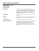
SPD Location Considerations Surge Protective Device (SPD) Location Considerations Environment The device is designed to operate in an ambient temperature range of -4 °F to +149 °F (-20 °C to + 65 °C) with a relative humidity of 0 to 95% noncondensing. The operating temperature of the LCD on the diagnostic display panel is -10 °C to +60 °C (+14 °F to +140 °F). Refer to the product catalog for further details on enclosures.
Electrical Electrical Voltage Rating DANGER HAZARD OF ELECTRIC SHOCK, EXPLOSION, OR ARC FLASH Confirm the SPD voltage rating on the module or nameplate label is the same as the operating voltage. Failure to follow these instructions will result in death or serious injury. Prior to mounting the SPD, verify that the device has the same voltage rating as the power distribution system in which it is installed.
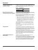
Electrical Terminals, Wire Size, and Installation Torque Terminals are provided for phase (line), neutral, and equipment ground connections. The SPD terminals accept a range of 12 AWG (3 mm2) to 2 AWG (34 mm2) copper wire for phase, neutral, and ground connectors. Torque connections to the following values. Table 3: Terminal Torque Power Connection AØ, BØ, CØ and N Ground Branch Circuit Overcurrent Protection and Disconnect Means Torque 35 lb-in.
Grounding Figure 2: Surge Protective Device Wiring Practice To load(s) SPD Phase A Phase B Phases Phase C Neutral Neutral Neutral bus Ground Ground Ground bus Interconnect wiring – Minimize length – Avoid sharp bends Panel Grounding WARNING HAZARDOUS TOUCH VOLTAGE • Connect the SPD ground terminal to the building grounding grid structure. • Use an appropriately sized equipment grounding conductor.
Grounding General The SPD device has SPD components connected from phase to ground. To prevent hazardous touch voltage on the SPD enclosure during normal operation or during SPD end-of-life, it is critical that there be a robust and effective connection to the building grounding structure. The grounding connection must utilize an equipment grounding conductor run with the phase and neutral (if present) connection of the power system. The SPD device should not be connected to a separate isolated ground.
Installation Installation DANGER HAZARD OF ELECTRIC SHOCK, EXPLOSION, OR ARC FLASH • Apply appropriate personal protective equipment (PPE) and follow safe electrical work practices. See NFPA 70E. • This equipment must only be installed and serviced by qualified electrical personnel. • Turn off all power supplying this equipment before working on or inside equipment. • Always use a properly rated voltage sensing device to confirm power is off.
Wiring Wiring DANGER HAZARD OF ELECTRIC SHOCK, EXPLOSION, OR ARC FLASH • Apply appropriate personal protective equipment (PPE) and follow safe electrical work practices. See NFPA 70E. • This equipment must only be installed and serviced by qualified electrical personnel. • Turn off all power supplying this equipment before working on or inside equipment. • Always use a properly rated voltage sensing device to confirm power is off.
Wiring Wiring Diagrams Without Integral Switch Figure 3: Single-Phase, Two- or Three-Wire, Grounded Installation NOTE 1: The neutral conductor is not present on two-wire grounded power systems. For these systems, bond the neutral and ground lugs together inside the SPD using 10 AWG wire.
Wiring Wiring Diagrams with Integral Switch Figure 5: Single-Phase, Three-Wire, Grounded Installation with Integral Switch NOTE 1: The neutral conductor is not present on two-wire grounded power systems. For these systems, bond the neutral and ground lugs together inside the SPD using 10 AWG wire.
Operation Operation DANGER HAZARD OF ELECTRIC SHOCK, EXPLOSION, OR ARC FLASH • Apply appropriate personal protective equipment (PPE) and follow safe electrical work practices. See NFPA 70E. • This equipment must only be installed and serviced by qualified electrical personnel. • Turn off all power supplying this equipment before working on or inside equipment. • Always use a properly rated voltage sensing device to confirm power is off.
Operation Audible Alarm Push the alarm enable/disable button to enable or disable the alarm (see Figure 8). If the green alarm LED is lit the alarm is enabled. If the green alarm LED is not lit the alarm is disabled. Surge Counter The surge counter displays the number of transient voltage surges since the counter was last reset. The counter is battery powered to retain memory in the event of a power loss to the diagnostic display panel.
Operation DANGER HAZARD OF ELECTRIC SHOCK, EXPLOSION, OR ARC FLASH • Use 600 Vac rated dry contact wiring. • Dry contact wiring must have less than 1/16 in. (1.6 mm) exposed wire from the dry contact block. • Maintain at least 1.0 in. (25 mm) separation between dry contact wiring and the power wiring in the enclosure. Failure to follow these instructions will result in death or serious injury. Care must be taken in installing the dry contact wiring because the terminals are on a moving door.
Maintenance and Troubleshooting Maintenance and Troubleshooting DANGER HAZARD OF ELECTRIC SHOCK, EXPLOSION, OR ARC FLASH • Apply appropriate personal protective equipment (PPE) and follow safe electrical work practices. See NFPA 70E. • This equipment must only be installed and serviced by qualified electrical personnel. • Turn off all power supplying this equipment before working on or inside equipment. • Always use a properly rated voltage sensing device to confirm power is off.
Maintenance and Troubleshooting Troubleshooting Figure 11: If a module shows two green indicator lights and the display panel shows a red phase indicator light, follow the Troubleshooting Flow Chart in Figure 11 below. Troubleshooting Flowchart NOTE: For further assistance, call APC Technical Support at 1-800-800-4272. START Red phase LED(s) lit. Alarm on? YES NO Is alarm Enable/Disable LED on? Check patch cable connections. Is Red LED(s) on? NO Check the voltage on each phase.
Installation and Operation Manual
Installation and Operation Manual 23
APC Worldwide Customer Support Customer support for this or other APC products is available at no charge in the following ways: • Visit the APC website to access documents in the APC Knowledge Base and to submit customer support requests. — www.apc.com (Corporate Headquarters) Connect to localized APC Web sites for specific countries, each of which provides customer support information. — www.apc.com/support Global support searching APC Knowledge Base and using e-support.