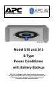
® w w w.apc.com Model S15 Shown Model S10 and S15 S-Type Power Conditioner with Battery Backup 990-1906 Copyright © 2005 American Power Conversion All rights reserved. The APC AV logo is a registered trademark of American Power Conversion. All other trademarks are the property of their respective owners.
Safety Information 1. 2. 3. 4. 5. 6. 7. 8, 9. 10. 11. 12. 13. 14. 15. Read this manual - Read all of the safety and operating instructions before installing and operating this device. Keep this manual - Retain this manual, and all of the safety information that came with this device. Warnings - Comply with all warnings presented in this manual, as well as any found on the device. Follow Instructions - Follow all operating and use instruction.
Safety Information - continued 16. Overloading - Do not overload the wall outlet where this device is being connected. Do not overload this device. Ensure the total load to this device does not exceed that which is listed in the Specifications section of this manual. 17. Openings - Do not push any object into the vents provided for cooling, as such an object may come into contact with high-voltage components and cause injury, death, or damage to the device.
Protect Your Investment Thank you for selecting APC's Model S10 or S15 Power Conditioner with Battery Backup. At APC, we know you have made an intelligent choice sure to reward you for many years. To ensure you receive all the benefits and protection which accompany your purchase, please take a few minutes to fill out and mail the enclosed Warranty Registration Card, or complete the online form at www.apcav.com.
Table of Contents Introduction 1-1 Proven Expertise… Proven Reliability 1-2 Safety Precautions 1-2 Package Contents 1-3 Unit Power Capacity 1-3 Features 1-4 Front and Rear Panels 1-6 Front Panel Controls and Indicators 1-6 Rear Panel Connectors, Indicator, and Circuit Breaker 1-9 Installation 2-1 Removing the Battery Pack 2-2 Placing the Unit 2-2 Inserting and Connecting the Battery 2-3 Powering On and Connecting Equipment 2-5 Performing the System Test 2-5 Status and Informational Screens 2-9 Connecting
x
C h a p t e r 1 Introduction Congratulations on your purchase of APC’s Model S10 or S15 Power Conditioner with Battery Backup (Model S15 shown in Figure 1). Either unit will protect your high performance audio and video (AV) system from damaging power surges, spikes and lightning, as well as power outages. Protection is guaranteed. Isolated noise filter banks and Automatic Voltage Regulation (AVR) will eliminate power as a source of audio and video signal degradation.
Proven Expertise… Proven Reliability From corporate data centers to home offices, APC is regarded as an innovator, designer and manufacturer of high-quality power protection solutions. With a proven reputation for Legendary Reliability , leading companies depend on APC every day to protect and support many of the most critical networks in the world, including those at Microsoft®, Toyota® Motor Sales, Inc., and IBM®.
Package Contents Your S10 or S15 Power Conditioner with Battery Backup package includes the following components: • 1 Power Conditioner with Battery Backup (battery pack included) • 1 Front Display Panel (Bezel) • 1 Input Power Cord • 3 Coaxial Patch Cables (S10 has 2) • 1 DC Trigger Cable • PowerChute Personal Edition Software CD • USB Interface Cable • 1 Telephone Patch Cable • 1 Ethernet Patch Cable (not available with S10) • 1 User Manual • 1 Equipment Protection Policy Sheet • 1 Warranty Card • 1 Rack-
Features The following are major feature of the Model S10 and S15. Pure Sine Wave Battery Backup Both models provide battery backup power to maintain pure, uninterrupted power for your home theater and automation systems in the event of a power blackout. Battery backup power not only prevents interruptions in your entertainment, it also prevents lost pre-sets, lost multi-media server data, damaged hard drives, and premature projector bulb wear and tear.
Rack-mountable Rack-mount hardware is included to mount the unit into any 4-post, 19" rack. See below for more information. Sequenced Turn ON/OFF This feature ensures that connected equipment is powered-up/down in the proper order and with the right amount of delay between the stages. It allows the user to program a delay into the sequence between 0 and 10 seconds. This delay eliminates transients that can affect connected components or cause the building circuit breaker to trip.
Front and Rear Panels The following sections describe the controls and indicators on the front and rear panels. Front Panel Controls and Indicators The front panel controls and indicators for the S10 and S15 Power Conditioners are identical, and are detailed in Figure 2. Each numbered callout refers to the numbered description found immediately following the picture. 1 2 14 3 13 4 12 11 5 10 6 9 7 8 Figure 2.
3 STATUS Push Button When pressed, provides unit status for: Input and Output Voltage, Input and Output Voltage, Input and Output Frequency, Telephone and Internet contact information, Model and Serial Number, Firmware (FW) Version number, Source (Standby, Battery, or Utility) and Estimated Runtime (in hours or minutes), Estimated Runtime (in hours) with a Fuel (as a percentage with bar graph) indication, as well as System Load (in watts), and Load (as a percentage with bar graph).
7 LINE OK Status Indicator When lit, input voltage from the utility is within acceptable range. If not lit, the Automatic Voltage Regulation circuit is active. If not lit, the Automatic Voltage Regulation circuit is correcting high or low voltage levels to maintain safe voltage conditions for connected components, or the unit is operating on battery power due to a blackout or extreme voltage level conditions.
14 DELAYED 2 Status Indicator When lit (blue), conditioned power is being supplied to equipment connected to the rear-panel outlets marked Delayed 2. 15 Removable Support Feet Feet can be unscrewed and removed to save space when rack mounting. Rear Panel Connectors, Indicator, and Circuit Breaker The rear panel connectors for the S10 and S15 Power Conditioner are detailed in Figure 3.
1 AC-Powered Outlets - The S10 and S15 Power Conditioner provides for connection of up to twelve (12) components. The outlets are arranged according to the type of filtering protection provided for a given component type. These Isolated Noise Filter Banks (INFBs) eliminate EMI and RFI that can negatively impact sound and video quality. APC recommends plugging your devices into the outlets as marked, in order to assure optimum protection for your equipment.
3 Surge Protected COAX/RF Connectors The surge protection feature prevents surges traveling over coaxial data lines from damaging the system. Connect the coaxial cable from the CATV or Cable Modem provider to the connector marked “IN”, connect other cables from the connectors marked “OUT” to the device(s) being protected (CATV box or Cable Modem - in some cases, the input for both are derived from the single cable from the provider - such as TV and Internet access through the same coaxial cable).
7 Input Power Connector Provides for connection of one end of the supplied AC power cord to the S10 or S15 Input Power Connector. Connect the other end to the AC utility power source (15 Amp, 120 Vac, 50-60 Hz). 8 DC TRIGGER Jacks Provides for connection of a component acting as a DC trigger, which controls turn on/off, as well as sequencing of the ‘DELAYED1 and 2’ outlet banks. The S10 and S15 also allows that DC signal to pass through to another connected component.
Proper installation of your new Power Conditioner is important. If installing the unit in a standard 19” rack, refer to the instruction sheet provided in the box which contains the slide rails, then return to this manual for further instructions. For all other installations, refer to the following paragraphs.
1-14
C h a p t e r 2 Installation This chapter contains the following sections: • Removing the Battery Pack • Placing the Unit • Inserting and Connecting the Battery • Powering On and Connecting Equipment • Performing the System Test • Status and Informational Screens • Connecting the Components • Setting Up the S10 or S15 Using the Front-Panel Controls 2-1
Removing the Battery Pack 1. Remove the battery retaining bar. 2. Pull the battery straight back. 3. Push in the retaining tabs to allow the battery to come out completely. Placing the Unit Proper placement of the S10 or S15 should be accomplished in accordance with the following: Caution: The S10 and S15 weigh approximately 60 pounds each. Two-person lift is recommended. Lift each unit carefully by firmly grasping both sides of unit in the middle.
4. Slide the unit into the rack so that the cleats mounted on the side of the unit fit within the track of the rack-mount rails. If the ears were mounted, screw the mounted ears into the rack to lock unit into position. (See the installation sheet located in the box marked, “Accessories.”) Note: Avoid placing other components directly on top of or behind the unit. Leave at least one inch of space on all sides to allow for proper air ventilation. Do not block the fan.
2. Push the Battery Wire Connector (Figure 5) into the hole located at the left of the Battery Pack. Ensure that the Battery Wire Connector is pushed into the hole and securely connected by gently pulling on the wire to see if it is attached to the connector. Figure 5. Battery Wire Connection 3. Install the battery retaining bar. 4. Install the front Bezel (Figure 6), by aligning the four pins located on the back-side of the Bezel to the holes at the left and right sides of the unit.
Powering On and Connecting Equipment 1. Power on the unit. 2. Connect the equipment. 3. Connect the data line cables. 4. Power on the connected equipment. Performing the System Test Before connecting equipment to the S10 or S15 Power Conditioner with Battery Backup, ensure that the unit is functional by connecting the AC Power Cord (provided) at the rear panel. Press the front panel power switch.
Figure 8. Model Identification Screen DELAYED OUTLET1: ON; DELAYED OUTLET1: OFF screen (Figure 9) — shows that power is available to the device (Tuner or Auxiliary component) that is connected to the rear-panel outlet marked Delayed 1. It also shows that power is not yet available to the devices that are connected to rear-panel outlets marked Delayed 2 (Subwoofer and/or Amplifier). Power to Delayed 2 devices will be available after the factory preset delay (5 seconds) has elapsed.
SELFTEST IS ON; ON-LINE SELFTEST screen (Figure 10) — shows that an On-Line Selftest is active. Figure 10. SELFTEST IS ON; ON-LINE SELFTEST Screen SELFTEST IS ON; ON-BATTERY SELFTEST screen (Figure 11) — shows that an On-Battery Selftest is active with the unit internally switched to power from the internal battery pack, which should already be connected within the unit. The On Battery LED is also lit during this test.
Figure 12. NO EXTERNAL BATTERY CONNECTED Screen SELFTEST RESULT; SELFTEST HAS PASSED screen (Figure 13) — shows that the Selftest ran successfully to completion. If the message “TEST HAS FAILED” is displayed, please contact APC Technical Support. Figure 13.
Status and Informational Screens The following sections describe the status and informational screens. Status Screens The most important status screens available after the Selftest has completed consist of: • INPUT VOLTAGE: XXXV; OUTPUT VOLTAGE: XXXV • SYSTEM LOAD:
SYSTEM LOAD:
Informational Screens The S10 and S15 Power Conditioners with Battery Backup provide the following informational screens, accessed using the STATUS push button: • Source: XXXXXXX screen • FW Version: XXXXXXX screen • Model Number and Serial Number screen • Phone Number and Technical Support Internet Address screen • Input Frequency; Output Frequency screen SOURCE: XXXXXXX; EST.
Firmware Version: XXXXXXX Screen This screen, shown in Figure 18, provides information about which version of the firmware is loaded in to the unit. Please have this information available any time you need to talk with APC Technical Support. Figure 18. Firmware Version: XXXXXXX Screen Model Number and Serial Number Screen This screen, shown in Figure 19, provides information about which Model you have purchased. It also provides the correct Serial Number for the unit.
Phone Number and Technical Support Internet Address This screen, shown in Figure 20, provides the world-wide telephone number for APC, as well as the Internet Web address for APC Technical Support and Customer Service. Please use this information any time you need to contact APC Technical Support or Customer Service. Figure 20.
INPUT FREQUENCY; OUTPUT FREQUENCY Screen This screen, shown in Figure 21, shows the actual input utility voltage frequency, as well as the actual voltage frequency being output to the connected devices. Note: At times, the frequency values on this screen may not match, This is due to the fact that separate circuits are used to make frequency measurements, and there is a time delay between the two circuits for updating this status screen. This condition is considered part of the normal operation of the unit.
Connecting the Components WARNING: Do not make telephone, cable, Ethernet, antenna, electrical, or ground system connections during a lightning storm. Failure to comply may result in personal injury or death. Note: Due to the unique filtering and surge protection provided by the S10 and S15, APC recommends connecting AV components as noted on the rear panel of the unit.
AUDIBLE ALARM Setting — when set to ON (Figure 22), provides an audible tone whenever the unit detects a problem with itself, or with an externally connected battery pack. In the OFF setting, the audible tone is silenced. Figure 22. AUDIBLE ALARM Setting Screen SENSITIVITY Setting — press the SETUP push button to advance to the Automatic Voltage Regulation (AVR) Sensitivity function. This feature adjusts how the UPS reacts to abnormal input voltage or momentary power fluctuations.
LOW Sensitivity — should be used when the UPS frequently goes to battery (even though the utility voltage appears normal). Example: If the unit goes ON BATTERY when your power amplifier is turned on. Figure 23. SENSITIVITY (HIGH) Setting Screen DISPLAY DIMMER Setting — lets you set a brightness level for the VFD of HIGH, LOW, or OFF. Use the SETUP push button to advance to the Display Dimmer screen (Figure 24).
GO TO BATTERY IF > XXXV Setting — lets you set a high voltage threshold for the unit, which will force it to switch to power from the Internal Battery Pack once the threshold has been reached. The settings range is from 134 to 144 volts (Figure 25). Figure 25. GO TO BATTERY IF > XXXV Setting Screen GO TO BATTERY IF < XXXV Setting (not shown) — lets you set a low voltage threshold for the unit, which will force it to switch to power from the Internal Battery Pack once the threshold has been reached.
OUTLET DELAY1 and OUTLET DELAY2 Setting (not shown) screens — lets you to set a defined time delay (0 to 10 seconds) for when the unit provides power to the rear panel outlet marked Delayed1 (TUNER/AUX) or Delayed2 (SUBWOOFER and/or AMPLIFIER). By setting this delay (Figure 26), it prevents power on or power off glitches from effecting other equipment connected to the unit. Figure 26.
BATREPDATE: XX/XX/XX Setting (Figure 28) — lets you input the exact date a replacement Battery Pack was installed in the unit. First, use the Up/Down Arrow push buttons to set the correct month, then press the SETUP push button to move the cursor to the day of the month field. Set the day of the month using the Up/Down Arrow push buttons. Again, press the SETUP push button to move the cursor to the year field, then set the year using the Up/Down Arrow push buttons. Figure 28.
DO RUNTIME CAL : screen (Figure 30) — lets you manually initiate a Runtime Calculation test to calibrate the internal measurements and should result in more accurate runtime estimates. This only needs to be done once every 6 months, or if the connected load changes significantly in size. Once initiated, the unit will operate on battery power until a low battery condition is reached. Figure 30.
Figure 32. DISPLY-BEEP TEST: Screen (all indicators/fields lit) SCREEN SAVER: ON/OFF screen (Figure 33) — lets you force the unit to alternate a message “S10 (or S15) POWER CONDITIONER WITH BATTERY BACKUP” continuously between the two lines of fields of the VFD. This feature helps to maintain display appearance quality, as well as add longevity to the VFD. Figure 33.
RESET TO DEFAULT: YES/NO Setting (Figure 34) — lets you force the unit to reset all previous settings to the factory default values. Simply advance to this screen, then press either Up/Down Arrow push button. The system will display two messages of: “INITIALIZING SETUP TO FACTORY DEFAULT” and “INITIALIZATION COMPLETE”. The system then returns to the RESET TO DEFAULT screen. Figure 34. RESET TO DEFAULT Screen Note: For convenience, you can set the unit to display any of the screens as the “default” screen.
2-24
C h a p t e r 3 Warranty Limited Warranty American Power Conversion (APC) warrants its products to be free from defects in materials and workmanship for a period of two years from the date of purchase. Its obligation under this warranty is limited to repairing or replacing, at its own sole option, any such defective products. To obtain service under warranty you must first obtain a Returned Material Authorization (RMA) number from customer support.
EXCEPT AS PROVIDED ABOVE, IN NO EVENT WILL APC BE LIABLE FOR DIRECT, INDIRECT, SPECIAL, INCIDENTAL, OR CONSEQUENTIAL DAMAGES ARISING OUT OF THE USE OF THIS PRODUCT, EVEN IF ADVISED OF THE POSSIBILTY OF SUCH DAMAGE. Specifically APC is not liable for any costs, such as lost profits or revenue, loss of equipment, loss of use of equipment, loss of software, loss of data, costs of substitutes, claims by third parties, or otherwise.
C h a p t e r 4 Contact Information Technical Support Internet Address: http://www.apc.com/support Email Support: support.apcc.com Toll free: (888) 88-APCAV General Information Address: American Power Conversion 132 Fairgrounds Rd. West Kingston, RI 02892 USA Toll free (U.S.
4-2
S p e c i f i c a t i o n s A Technical Specifications The following table shows the technical specifications for the Model S15 and S10 S-Type Power Conditioner with Battery Backup.
Models S15 S10 External Battery Pack (SBATT) INPUT Voltage Range for Operation on Utility 90V – 144V Same N/A Nominal Voltage 120 Vac Same 48 Vdc Allowable Frequency for Operation on Utility 47 – 63 Hz Same N/A Rated Input Current 12 Amps 9 Amps N/A Circuit Breaker Rating 15 Amps 15 Amps N/A # of Outlets 12 (all outlets are surge protected, conditioned, regulated and battery backed up) Same N/A Outlet Type NEMA 5-15R Same N/A Rated VA Capacity 1440 VA 1000 VA N/A Rated Wa
Transfer Time to Battery During Blackout 7ms typical, 10ms maximum Same N/A Battery Type/Quantity 4 12V/9A hr Sealed Lead-Acid, Maintenance Free Same 8 12V/9A hr Sealed Lead -Acid, MaintenanceFree Typical Recharge Time to 90% Capacity <8 hrs Same N/A Battery Service Userreplaceable, Hotswappable Same Not UserServiceable Battery Life 2-5 Years (Depending on use, environment, and temperature) Same Same Battery Runtime 20 minutes (half load) or 7.
Data Line Protection Jacks RJ45 Same N/A COAX 3 pair + splitter 3 pair N/A Ethernet 1 pair 10/100bT None N/A Telephone/DSL 2 line, 4 wire with splitter 1 line, 2 wire protection N/A DC Trigger Two 3.5mm mini-jack plugs (5-30V) Same N/A 17 x 5.25 x 18.55 in. Same 17 x 3.5 x 18.55 in. PHYSICAL Unit Dimensions 43.2 x 8.9 x 47.1 cm 43.2 x 13 x 47.
T r o u b l e s h o o t i n g B Troubleshooting Problems This appendix describes possible causes and solutions for the following problems: 1. Unit will not turn on. 2. Connected equipment reboots or turns off during or after the unit switches to battery power. 3. Replace Battery” LED is illuminated. Note: The VFD screen will display any faults or warning conditions that occur along with a message explaining what action to take.
Possible Cause: No power or insufficient power available at the wall outlet. Solution: Ensure the wall outlet has good power by using a voltmeter or by plugging in another device. Note: The unit will not turn on and accept incoming utility power if the power is out of range. The unit can still be “cold-started” using battery power, by pressing and holding the power switch until the unit beeps. Possible Cause: Circuit Breaker has tripped. Solution: Check both home and unit circuit breakers.
Replace Battery” LED is illuminated. Possible Cause: Battery is nearing the end of its useful life. Solution: If the unit’s warranty is more than 2 years from date of purchase, a Replacement Battery Cartridge (part# RBC63) can be ordered from your AV dealer. Address: American Power Conversion 132 Fairgrounds Rd. West Kingston, RI 02892 USA Email Support: support.apcc.
B-4