Silcon DP300E Series 480V 120–160kVA Installation Guide Copyright © 1999 APC Denmark A/S Due to continuous product development information given in this guide is subject to change without notice. 7OH0006 US rev. 03 Installation Guide Silcon DP300E Series 480V 120-160kVA 7OH0006 US rev.
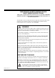
IMPORTANT SAFETY INSTRUCTIONS SAVE THESE INSTRUCTIONS This guide contains important instructions for your Silcon DP300E UPS that should be followed during installation and maintenance of the UPS and batteries. The installation and use of this product must comply with all national, federal, state, municipal or local codes that apply. If you need help, please call APC’s toll free technical support at: 1-877-287-7835 (1-877-2UPS-TEK). WARNING! UPS units contain hazardous AC and DC voltages.
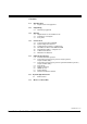
Contents 1.0 Introduction 1.1 2.0 Unpacking 2.1 3.0 5.3 5.4 5.5 5.6 5.7 5.8 Parallel/redundant operation Diagrams for service bypass panel for single operation, single and dual utility Diagrams for service bypass panel for parallel redundant operation, single and dual utility Relay board Seismic anchoring NEMA 12 cover Remote display Isolation transformer module System Specifications 6.1 7.
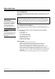
Introduction 1.0 Introduction The information provided in this installation guide is of a general nature for a local authorized electrical installer. Please refer to local/national electrical codes for more information. WARNING! The UPS and related equipment are very heavy. To prevent personal injury or equipment damage, please use extreme care when handling and transporting the UPS cabinet and related equipment.
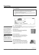
Unpacking 2.0 Unpacking 1. 2. 3. 4. Unpack the system. Check that the type sign placed inside on the front door corresponds to the ordered system, especially with respect to input / output voltages. To simplify later identification of the installed system – please transfer the data from the type sign to the below blank copy. Transport the system to the installation site by lifting underneath by means of a fork lift.
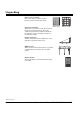
Unpacking Battery rack or cubicle. The rack or cubicle is used for external batteries, for storing the battery bank. Battery cubicle Battery rack Isolation transformer. The isolation transformer is used, when galvanic isolation is required from the source to the conditioned power. This transformer should also be used if the source is something other than a grounded Wye supply. Seismic Anchoring. Seismic anchoring is used for stabilization of the UPS, when needed for seismic areas. NEMA 12 cover.
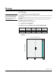
Placing 3.0 Placing WARNING! Do not stand on or place any object on any UPS cabinet or UPS cubicle due to personal and product safety. 3.1 Requirements on the Installation Site The system is designed with parts accessible from front or top and cable entries from top or bottom. The system can be placed close to walls, only free space for front door opening has to be ensured. Sufficient cooling and service clearance must be ensured by a free space of min. 3 feet above and in front of the system.
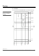
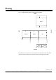
Placing 3.3 Foot Prints 3.3.1 Foot prints Silcon DP3120E–DP3160E – 67.00 / 1600 in./mm cubicle 62.99/1600 62.05/1576 NOTE: Dimensions in drawings are stated in inches / millimeters respectively. COM DC UTILITY 1 59.25/1505 59.06/1500 50.93/1280 OUTPUT 47.64/1210 42.40/1077 30.59/777 FRONT REAR UTILITY 2 39.65/1007 26.65/677 23.90/607 3.74/95 1.81/46 1.02/26 0 6.14/156 7.87/200 14.37/365 15.94/405 25.98/660 31.50/800 30.47/774 0.94/24 0 7OH0006 US rev.
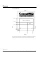
Placing 3.3.2 Conduit entrance plate in bottom of the system REAR LEFT RIGHT Utility 1 30.39/771.9 DC 19.78/502.5 Output 10.14/257.5 0 Utility 2 COM COM FRONT For cable entry, holes will need to be punched into the UPS. Follow the diagram for proper orientation of the power and control wires to be brought into the UPS. 7OH0006 US rev.
Placing 3.3.3 Top cable entry REAR 17.72/450 Utility 1–2 / Output / DC 11.61/295 COM LEFT RIGHT 7.68/195 26.12/663.5 16.28/413.5 3.31/84 0 0 FRONT For cable entry, holes will need to be punched into the UPS. Follow the diagram for proper orientation of the power and control wires to be brought into the UPS. 7OH0006 US rev.
Connection 4.0 Connection WARNING! Before continuing, read the warnings on page 2 of this manual. NOTE! Always separate AC, DC, and communication cables. See chapter 4.1.3. 4.1 Connecting the Silcon DP300E This section is for connecting the UPS unit itself. Before connection, refer to section 5.0 Options/Accessories to ensure that the UPS and options are properly interfaced together during the installation process. 4.1.
Connection NOTE: This UPS must be fed from a grounded WYE service, 3 or 4 wire to UPS. 4.1.2 Connecting AC and DC power cables NOTE: UPS system must be fed with an A-B-C clockwise rotation. NOTE: UPS input and UPS output conductors must be in separate conduits. NOTE: UPS AC and DC conductors must be in separate conduits. NOTE: Battery 1 and battery 2 DC conductors must be in separate conduits. NOTE: UPS power conductors and UPS control wiring must be in separate conduits.
Connection Dual utility connection FRONT E L1 L2 L3 N L1 L2 L3 N Utility 2 - X002 Output - X005 Ext. DC Utility 1 - X001 NOTE: Ground connection in the bottom of the cabinet. 7OH0006 US rev.
Connection Right side view Ext. DC Utility 1 X001 Left side view Utility 2 X002 Output X005 NOTE: Ground connection in the bottom of the cabinet. 7OH0006 US rev.
Connection 4.1.3 Separation of AC from DC1 and DC2 Two pieces of polycarbonate are supplied along with the UPS and are used for separating the AC from DC1 and DC2. The length of the polycarbonate is delivered as standard top entry. If bottom entry is used, the polycarbonate has to be cut for proper installation. 4.1.4 Top or bottom entry If top cable entry is used, the copper angle bar has to be moved to bottom. Unscrew bolt, take out the split, move the angle bar down, insert split, and tighten the bolt.
Connection 4.1.5 Dual and single utility supply WARNING! UPS units contain hazardous AC and DC voltages. A qualified electrician must install the UPS, AC line service, and external batteries according to national and local codes and must be familiar with batteries and battery installation. Before installing, maintaining, or servicing the UPS, shut off the UPS and disconnect all sources of AC and DC power.
Connection NOTE: Utility 1 and 2 voltage and frequency tolerance, see specification in chapter 6. Utility 1 or 2 support the load in normal operation and the load through the static and service bypass switch as well. Working principle of single utility (1utility supply): Q3 Utility 1/2 Output Q1 Q2 Utility 1/2 DP300E 4.1.6 Changing from dual to single utility input Follow below the description for changing from dual to single input.
Connection 1. Remove fiber bar (55322) by unscrewing bolts and by mounting copper bars as below. Dual utility 2. Single utility Change around the connector in Con3 to Con1. 7OH0006 US rev.
Connection NOTE: This UPS is intended to be supplied from a grounded WYE –service, either 3 or 4 wire. External power conductors and overcurrent protection AC Utility 1 MCCB [A] AC Utility 1 conductors per phase a) DP3120E – 480V NOTE: Ensure clockwise rotation of utility input voltage!! Max. power cable size: 500 kcmil. DP3160E – 480V NOTE: All external cable dimensions are recommended. Please refer to local legal provisions.
Connection 4.1.
Connection 4.1.7 Grounding 4.1.7.1 System grounding If none of the UPS neutral inputs are connected to a grounded service neutral conductor per NEC per local code requirement, provisions have to be made as follows: a. The bonding wire is mounted between output terminals X005:N/E and equipment ground bar in bottom of unit. b.
Connection 4.2 System Integration Interface 4.2.1 Introduction Single Utility NOTE: Use of the same designations in your diagrams make information exchange much easier. NOTE: Refer to chapter 4.1.6 Changing from dual to single utility input. Dual Utility WARNING! System Integration Interface can receive high voltage from external alarm and signal circuit field wiring even if all AC and DC sources are off.
Connection Besides previous mentioned the SII-board also have input facilities for emergency shut down and temperature compensation of the charge voltage for external battery (used together with the battery monitor, see also User Guide). “Battery operation” and “Common fault” are the two main status relay signals also coming from the SIIboard. NOTE: When installing UPS systems with Emergency Power Off (EPO) all input sources must be provided with disconnecting device when activating EPO 4.2.
Connection X004 X004 LED's OK for operating: 8 Battery MCCB2 7 Battery MCCB1 6 +12V 5 Auxiliary contacts on: 4 Internal battery fuse F021 (NO) position 3 Internal battery fuse F020 (NO) position 2 1 White Black Temperature sensor, external battery S001 1 Internal battery temperature sensor 2 External battery temperature sensor S001 X003 (Charge voltage compensation: -0.576V/°C) X003 Input signals: Contact load: TTL 12 Iso. trafo temp. 11 switch (NC pos.
Connection X012 X005 X012 Auxiliary contacts on: 4 External battery 3 Fuse/MCCB2 (NO) position 2 External battery 1 Fuse/MCCB1 (NO) position Output relays: 277V/8A, 0,3VA-2kVA 14 Battery operation signal.
Connection 4.3 Communication interface – ComInterface 4.3.1 Introduction The ComInterface having 2 ports - is used when an interaction between UPS and e.g. a computer system has to be established. The main purpose is to ensure monitoring and if needed, a controlled shut down of the computer in case of failures in the utility supply. 4.3.2 Connections Smart slot, see chapter 4.4 X008, 25 pin SUB D male. Serial port RS232. For service use. X005, 25 pin SUB D female. ComPort. 7OH0006 US rev.
Connection 4.4 SmartSlot for Silcon DP3120E – DP3160E A UPS system alone provides excellent protection from brief power problems. However, during an extended power outage an unattended computer system will eventually shut down due to battery capacity exhaustion. To prevent data corruption when the UPS shuts down, the computer must be informed by the UPS of impending shut down and take appropriate file-saving measures. This important function is called UPS monitoring.
Connection Installing accessories – procedure: To install accessories, perform the following steps. 1. 2. Make sure that the Silcon DP300E is powered off. Install the SmartSlot accessories into the housings on the front of the chassis. See the instructions supplied with the accessories and “Priority of APC accessories.” If your UPS has one SmartSlot accessory slot If your UPS has exactly one SmartSlot accessory slot, use this accessory slot for the SmartSlot device with the lowest priority.
Connection 4.5 Installing the UPS in a computer room If installing the UPS system in a computer room the following MUST be provided at installation site: 1. – The system can only be installed with external batteries. – Alternate supplier’s battery cubicle must be UL Listed. If used in computer room it must be approved for use in computer room. – When APC battery cubicle is not used, the proper DC disconnects/overcurrent must be used in accordance with the APC Design Guide.
Connection The other part of the EPO switch has interconnection to an electronic control system (not supplied by APC), supplying the tripping function in the MCCB and switchgear with an external 277Vac or 480Vac 50/60Hz supply, supported from Utility 2, if available, or Utility 1 and from the output of the UPS before Q002. This combination of 2 break function, one for the UPS system and one for external switchgear makes it possible to make a quick shutdown of the total system in case of emergency.
Connection 4.5.2 Emergency Power Off (EPO) for Silcon DP300E If installing the UPS system in a computer room, the installation MUST contain external batteries with MCCB’s and switchgear provided with trip function – approved for use in computer room – for EPO tripping of MCCB’s and switches. See chapter 4.5.1 for details. By the following, the system is installed with dual utility. Q3 Output Utility 2 User supplied external PSU.
Connection By the following, the system is installed with single utility. Q3 Output User supplied external PSU. Used for tripping of MCCB’s in external battery cubicle or battery room and switches in switch gear. Utility 1/2 Q1 Q2 UPS Ext. DC Matrix single utility DC Utility 1 Operation mode 0 0 Off Bypass op. 0 1 1 0 Batt. op. 1 1 Normal op. Nothing to trip Batt. Bypass 7OH0006 US rev.
Connection 4.6 Cubicles for batteries IMPORTANT SAFETY INSTRUCTIONS a) Servicing of batteries should be performed or supervised by personel knowledgeable of batteries and the required precautions. Keep unauthorized personnel away from batteries. b) When replacing batteries, replace with the same number and type as installed. See also the installation guide from battery supplier, on how to install. c) CAUTION - Do not dispose of battery or batteries in a fire. The battery may explode.
Connection 4.6.1 Cubicle for batteries 4.6.1.1 Safety - Warnings WARNINGS The total system contains HAZARDOUS AC/DC VOLTAGES and is supplied from more power sources.
Connection 4.6.1.6 Introduction Warning With reference to Local/National Code use: 1. 2. Additional insulating material Insulating tools WARNING The battery bank is sub-divided into two separated DC busses “batteries”: 1. Battery 1 is a series connection of a number of batteries, drawing on next page shows the principle. No. 1 and no. 2 containing 32 batteries (can also be 64, 96, or 128 batteries depending on the total battery solution), return in no.
Connection Principal diagram Bat. 1+ Bat. 1– NOTE: See Installation Guide from battery cubicle supplier for installation. F002 Bat. 2– Bat. 2+ F001 No. 3 No. 1 No. 4 Battery 1 No. 2 Battery 2 No. 5 No. 6 Connecting the batteries to the Silcon DP300E, see chapter 4 for DC connections. 7OH0006 US rev.
Connection 4.6.1.7 Before Starting-up WARNING 1. Ensure that no electric power supply source has been connected to the Silcon DP300E for at least 5 min. 2. Ensure that DC breakers in cubicle are in position “OFF”. 3. Place the switch S001 on the Silcon DP300E System Integration Interface in the position “External battery temperature sensor”. 7OH0006 US rev.
Connection 4.6.1.8 Connecting the units Regarding cables – please refer to point 4.0: Connection and to below diagram 4.6.1.9. The following procedure is recommended: 1. Connect the Silcon DP300E terminals X004 and X012 on the System Integration Interface to the terminals X009, X010, and X012 in the battery box. These wires must be separated from the power cables. 2. Connect a possible external trip circuit to the X011 terminal in the battery box. 3.
Connection 4.6.1.9 Diagram – Silcon DP300E with battery cubicle System Integration Interface X003 X004 + – + – G X004 1 2 6 7 8 X012 1 2 3 4 X001 1 2 3 4 Silcon DP300E MCCB trip for EPO + – + – G X003 X004 1 2 1 2 3 X012 X009 1 2 3 4 X010 1 2 X011 Battery Cubicle 7OH0006 US rev.
Connection 4.7 MCCB-box for external batteries The MCCB-box is used for overcurrent and shortcircuit protection when the Silcon DP300E is installed with an external battery. 4.7.1 General arrangement MCCBbox Silcon DP300E Battery 4.7.2 Front view (closed door) Front view 7OH0006 US rev.
Connection Front view (Open door) 7OH0006 US rev.
Connection 4.7.3 Mounting and Connection B NOTE: All external cable dimensions are recommended. Please refer to local national legal codes. 4 x Ø 10mm on 648 x 448 A Centres for fixing holes in rear of enclosure NOTE: Ensure correct polarity at connection of DC cables. NOTE: Terminal for Equipment Grounding Conductor is marked External power conductors, overcurrent protection & mechanical sizes Type NOTE: Grounding, please refer to local legal provisions.
Connection 4.7.4 Silcon DP300E with external battery via MCCB-box Silcon DP300E X003 X004 + – + – G System Integration Interface X004 X012 X001 1 2 6 7 8 1 2 3 4 1 2 3 4 MCCB trip for EPO Temp. sensor + – + – G X001 X002 1 2 3 1 2 3 X009 X010 4 1 2 X011 MCCB-Box G X004 + Battery 2 G X003 + Battery 1 7OH0006 US rev.
Options/Accessories NOTE: Only use the original control cable delivered with the parallel board. 5.0 Options/Accessories 5.1 Parallel/Redundant operation The parallel board. NOTE: The control cables must be separated from the AC and DC power cables. NOTE: Common battery pack is a technical possibility. However, APC recommend separate battery pack due to a higher safety degree in connection with redundant/parallel operation. The UPS system is prepared for both solutions. Introduction.
Options/Accessories Control cables. The external multicable is terminated with a 15 pin SUB-D plug in both ends. Pin 1 to pin 1, pin 2 to pin 2, and so on up to pin 15 - except pin 8, which is not connected. Shield is connected to plug cover in both ends. The terminals X020 and X021 for the control cables are situated on the parallel board. X020 in UPS1 is connected to X021 in UPS2, X020 in UPS2 is connected to X021 in UPS3 and so on. X020 in last UPS is connected to X021 in UPS1. Power cables.
Options/Accessories 5.2 Diagrams for Service Bypass Panel for Single Operation, Single and Dual Utility 5.2.1 Diagram for Service Bypass Panel for Single Operation, Single Utility SBP Q003 System Input System Output Q002 Internal output fuse Q001 Silcon DP300E MCCB-box Battery 7OH0006 US rev.
Options/Accessories 5.2.
Options/Accessories 5.2.
Options/Accessories 5.2.
Options/Accessories 5.2.
Options/Accessories 5.2.6 Mounting & Connection NOTE: All external cable dimensions are recommended. Refer to local/national legal codes. WARNING: At 100% switch mode load the neutral conductor shall be rated for 173% output phase current. NOTE: φ is symbol for “phase”. is symbol for “Risk of electric shock”. Terminal for Equipment Grounding Conductor is marked NOTE: Grounding, refer to local/national legal codes. NOTE: Ensure correct phase connection of inputs and outputs. 7OH0006 US rev.
Options/Accessories 5.3 Diagrams for Service Bypass Panel for Parallel Redundant Operation, Single and Dual Utility 5.3.1 Principle Diagram for Service Bypass Panel for Parallel Redundant Operation Single Utility SBP Q003 System Input Q004 System Output Q002b Q002a Q001a Q001b X020 X021 Control cables Silcon DP300E MCCB-box Battery X020 X021 Silcon DP300E 7OH0006 US rev.
G L1 L2 L3 N Installation Guide Silcon DP300E Series 480V 120-160kVA X002 G + - + - X001 G X004 + - + - X003 X002 L1 L2 L3 N Silcon DP300E X001 G G L1 L2 L3 N X002a X001 L1 L2 L3 N Utility input 1 G 3 3 1 5 6 6 7 7 8 8 X010a 1 2 3 X009 8 1 1 2 3 X010 X012 2 3 4 4 1 2 X011 1 X003 5 X021 G E X002b G G X004 X002 G G G 3 3 1 5 6 6 7 7 8 8 X010a 1 9 2 3 X009 8 1 1 2 3 X010 X012 2 3 4 4 System Integration Interface 4 5 X003 4 X004 2 6
G L1 L2 L3 N X002 G + - + - X001 G X004 + - + - X003 X002 L1 L2 L3 N Silcon DP300E X001 G G L1 L2 L3 N X002a X001 L1 L2 L3 N Utility input 1 G 2 2 2 1 5 6 6 7 7 8 8 X010a 1 2 3 X009 8 1 1 2 3 X010 X012 2 3 4 4 X003 5 X021 G E X002b G G X004 X002 G G G 2 2 2 1 5 6 6 7 7 8 8 X010a 1 9 2 3 X009 8 1 1 2 3 X010 X012 2 3 4 4 System Integration Interface 4 5 X003 4 X004 6 7 3 3 MCCB-box 1 1 1 G X003 5 + X001 2 3 1 2 X0
G L1 L2 L3 N Installation Guide Silcon DP300E Series 480V 120-160kVA G X002 + - + - X001 G X004 + - + - X003 X002 L1 L2 L3 N L1 L2 L3 N X006a Utility input 2 X005 L1 L2 L3 N Silcon DP300E X001 G G L1 L2 L3 N X002a Utility input 1 X001 L1 L2 L3 N G G G 2 2 2 1 5 6 6 7 7 8 8 X010a 1 2 3 X009 8 1 1 2 3 X010 X012 2 3 4 4 X003 5 X021 G E X002b G G X004 X002 G G X002 L1 L2 L3 N G G 2 2 2 1 5 6 6 7 7 8 8 X010a 1 9 2 3 X009 8 1 1 2
G L1 L2 L3 N X002 G + - + - X001 G X004 + - + - X003 X002 L1 L2 L3 N L1 L2 L3 N X006a Utility input 2 X005 L1 L2 L3 N Silcon DP300E X001 G G L1 L2 L3 N X002a Utility input 1 X001 L1 L2 L3 N G G G 2 2 2 1 5 6 6 7 7 8 8 X010a 1 2 3 X009 8 1 1 2 3 X010 X012 2 3 4 4 X003 5 X021 G E X002b G G X004 X002 G G X002 L1 L2 L3 N G G 2 2 2 1 5 6 6 7 7 8 8 X010a 1 9 2 3 X009 8 1 1 2 3 X010 X012 2 3 4 4 System Integration Interface
Options/Accessories 5.3.6 Mounting and Connection NOTE: All external cable dimensions are recommended. Refer to local/national legal codes. WARNING: At 100% switch mode load the neutral conductor shall be rated for 173% output phase current. NOTE: φ is symbol for “phase”. is symbol for “Risk of electric shock”. Terminal for Equipment Grounding Conductor is marked NOTE: Grounding, refer to local/national legal codes. NOTE: Ensure correct phase connection of inputs and outputs. 7OH0006 US rev.
Options/Accessories 5.4 Relay Board Relays. All relays are “fail safe”, i.e. relay coil is energized when there is no alarm. The relay is shown in alarm position. 1 Max. load: 8.0A - 277VAC 0.3A - 60VDC Min. load: 0.05A - 6VAC 0.05A - 6VDC 2 3 7OH0006 US rev.
Options/Accessories 5.4.1 Relay Board, relay functions NOTE: If “Communication to controller lost” alarm is active, ALL relays will indicate failure. ## Delay is programmable from the display under “Common fault delay”, see User Guide. Settings: 0, 10, 20, 30 seconds Relay No.
Options/Accessories 5.5 Seismic anchoring 57.56/1462 55.98/1422 37.95/964 FRONT 36.38/924 22.20/564 20.63/524 7.01/178 5.43/138 0 3.21/815 28.28/7185 0 7OH0006 US rev.
Options/Accessories 8 seismic anchoring angles IMPORTANT: Remember to tighten all bolts in the 8 angles to the floor. Bolts for the floor are not enclosed. 5.5.1 Mounting seismic anchoring 16 holes for Ø10mm bolts have to be drilled according to dimensioned sketch, where the UPS system is to be placed. The system is placed after drilling the holes, then 8 angles for seismic anchoring are to be fitted into the bars, see above. The angles are then tightened in the holes.
Options/Accessories 5.6 NOTE: NEMA 12 is impossibel with top cabel entry. NEMA 12 cover (IP31) 5.6.1 Mounting NEMA 12 cover • Replace all screws on the top cover (4) with distance stays (5) and plastic locking washer (6). • Mount the NEMA 12 cover with plain washer (10), spring washer (11) and screw (12) on the 4 distance stays. Front view with NEMA 12 cover 5 6 4 5.6.1.1 Front view with NEMA 12 cover 7OH0006 US rev.
Options/Accessories 5.7 Remote display 5.7.1 Introduction The remote display unit provides the Silcon DP300E series with the possibility to display condition data at remote sites of up to 25 meters away from the Silcon DP300E unit. For extension of communication distance, see section 5.7.1.1 below. The remote display can easily be connected to the Silcon DP300E series via the serial communication ports on the communication interface. To obtain a transmission distance of 3.
Options/Accessories Table 1: Examples of communication extension to remote display. Standard (RS232) RS485 Current Loop Optic fibre Max. distance 25 meters 1,200 meters 3,200 meters 2,000 meters Converter Manufacture Art.
Options/Accessories 5.7.2 Installation of remote display 5.7.2.1 Connecting RS232C and utility adapter Back view 1. Loosen the 4 screws by turning 180° 2. Remove front cover Cabel entry from bottom and back NOTE: All alarm and signal circuit field wiring shall be rated 300V minimum. Back view Front view 3. Mount the backplate DP9P Utility adapter 4. Connect cables 7OH0006 US rev.
Options/Accessories 5.7.2.2 Remote display power supply The remote display power supply is a normal AC power supply with no battery backup. This means that if data transmission with the Silcon DP300E has to continue during break down of the commercial utility, the remote display has to be supplied from the Silcon DP300E or another uninterruptible power source. 5.7.2.
Options/Accessories 5.8 WARNING: For dual utility the same type of isolation transformers always has to be used for the 2 utility input. NOTE: Ensure correct phase connection of inputs and outputs. WARNING: At 100% switch mode load, the neutral shall be rated for 173% output phase current. NOTE: All external cable dimensions are recommended. Refer to local/national legal codes. NOTE: Grounding, refer to local/ national legal codes. NOTE: is symbol for “risk of electric shock”.
Options/Accessories 5.8.4.1 External temperature alarm cable Voltage rating must be 600V. Cable size can be 18 to 14 AWG. 5.8.5 Recommended cable lugs and crimping tool types See section 4.1.6. 5.8.6 Input Isolation transformer - Diagram Delta-WYE configuration (Dyn11) L1 L1 L2 L2 L3 L3 Output N E G G 1 2 5.8.7 Temp. Alarm Grounding the isolation transformer 5.8.7.1 System grounding See the installation guide for Isolation Transformer. 5.8.7.
Options/Accessories 5.8.8 Principal diagram 5.8.8.1 Single utility and single system SBP Utility Supply Output DP300E 5.8.8.2 Single utility and redundant system SBP Utility Supply Output DP300E DP300E 7OH0006 US rev.
Options/Accessories 5.8.8.3 Dual utility and single system SBP Utility Supply 2 Output Utility Supply 1 DP300E 5.8.8.4 Dual utility and redundant system SBP Utility Supply 2 Output Utility Supply 1 DP300E DP300E 7OH0006 US rev.
System specifications 6.0 System specifications 6.
How to Contact APC 7.0 How to contact APC For more information call: Tel: (800) 800-4APC - US & Canada Tel: (401) 789-0204 - Worldwide APC Corporate 132 Fairgrounds Road West Kingston, RI 02892 USA Tel: (401)789-0204 Fax: (401)789-3710 Internet: apcinfo@apcc.com PowerFax™: (800) 347 - FAXX APC Web site: www.apcc.com APC Denmark A/S Silcon Allé DK-6000 Kolding Tel: (+45) 75 54 22 55 Fax: (+45) 75 54 27 89 Product Support E-mail: silcontech@apcc.