Interface Expander AP9607 ®
Thank You! Thank you for selecting the UPS Interface Expander (AP9607). It has been designed for many years of reliable, maintenance-free service in combination with your American Power Conversion (APC) uninterruptible power supply (UPS). APC is dedicated to the development of high-performance electrical power conversion and control products. We hope that you will find this product a valuable, convenient addition to your computing system.
Contents Introduction . . . . . . . . . . . . . . . . . . . . . . . . . . . . . . . . . . . . . . 1 Overview 1 Features of the Interface Expander 2 Hardware and software requirements 3 Choosing cables 4 Safety warning 4 Product Description . . . . . . . . . . . . . . . . . . . . . . . . . . . . . . . . 5 Interface Expander panel 5 Basic monitoring ports 5 Configuration DIP switches 5 Status LED 6 Key Concepts . . . . . . . . . . . . . . . . . . . . . . . . . . . . . . . . . . . . .
Contents continued Connecting to Protected Devices . . . . . . . . . . . . . . . . . . . . . . 17 Connection procedure 17 Connecting the Interface Expander 18 Configuring the Interface Expander . . . . . . . . . . . . . . . . . . .
Introduction Overview The UPS Interface Expander (AP9607) is an American Power Conversion (APC) SmartSlot™ accessory that provides two additional computer interface ports for your APC UPS equipped with a SmartSlot accessory slot. It allows the UPS to work in conjunction with your power management software to provide safe system shutdown in extended power outages for up to three network servers or other devices.
Introduction continued Features of the Interface Expander The Interface Expander: • Mounts in all APC devices equipped with a SmartSlot accessory slot. • Works well in a heterogeneous network. Servers running different operating systems can monitor the same UPS simultaneously. • Supports advanced or simple signaling on the advanced port of the UPS. • Can delay shutdown of the UPS until all servers have shut down gracefully. • Allows you to restart hung servers.
Introduction continued Hardware and software requirements The Interface Expander requires: • An APC device equipped with a SmartSlot accessory slot. SmartSlot devices include—but are not limited to—the APC UPSs in the next item. • An APC UPS of one the following models: – Smart-UPS®, except models AP250, AP400, AP600, AP900, AP1250, AP2000, SUVS420, SUVS650, SUVS1000, SUVS1400, SU620. – Matrix-UPS™, except models with serial numbers less than x9412. – Symmetra™ PowerArray™.
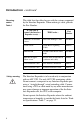
Introduction continued Choosing cables: Table 1 This table lists the cables for use with the systems supported by the Interface Expander. When ordering a cable, provide the Part Number.
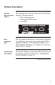
Product Description Interface Expander panel: Figure 1 The following figure shows the front panel of the Interface Expander. The panel contains: • 2 Basic monitoring ports • 4 Configuration DIP switches • a status LED Figure 1:Interface Expander panel Basic monitoring ports The two computer interface ports on the Interface Expander are called Basic ports because they supply simple UPS signaling for On Battery and Low Battery conditions in the UPS.
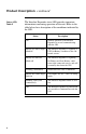
Product Description continued Status LED: Table 2 The Interface Expander status LED provides important information concerning operation of the unit. Refer to the table below for a description of the conditions indicated by the LED. Status On Normal operation. The Interface Expander is on and communicating with the UPS. Mostly on, with a single blink off The Interface Expander is signaling a UPS On Battery condition to the connected servers.
Key Concepts Simple versus smart signaling: Table 3 The communication between an APC UPS and a connected server can be of two types: simple signaling or smart signaling. This table provides information that distinguishes the two types.
Key Concepts continued Master server versus Interface Expander servers A “master” server is a server connected to the (Advanced) computer interface port of the UPS. This server uses PowerChute plus, configured for smart signaling, to monitor and control the UPS. Although the Advanced port on the UPS can provide simple signaling, we strongly recommend using it for smart signaling with the advanced capabilities of PowerChute plus.
Key Concepts continued Configuring PowerChute plus for simple signaling To use PowerChute plus on a server connected to the Interface Expander, configure PowerChute plus for simple signaling. Use either one of these procedures. 1 (Re)install PowerChute plus. When the installation program prompts for the UPS Type, select “BackUPS” and continue with the installation, including a reboot of the system. 2 Run PowerChute plus and connect to the UPS.
Key Concepts continued Low Battery signal The Interface Expander generates a Low Battery signal when it detects a Low Battery condition at the UPS, regardless of whether the UPS is on battery. The Interface Expander generates a Low Battery signal under certain other conditions according to the configured shutdown mode (see “Configuring the Interface Expander” on page 19), when it may force a Low Battery signal and an On Battery signal, causing the servers to shut down.
Key Concepts continued Setup overview To set up the Interface Expander, you will be required to perform the following procedures as applicable: 1 Determine which SmartSlot accessory slot you will use for the Interface Expander. See “Multiple SmartSlot Installation” on page 12. 2 Install the Interface Expander into the SmartSlot accessory slot of the UPS or other device. See “Installation” on page 15. 3 Connect the protected devices. See “Connecting to Protected Devices” on page 17.
Multiple SmartSlot Installation Introduction If your UPS configuration uses more than one SmartSlot device, you must install them in the correct order for them to work together properly. Priority of SmartSlot devices: Table 4 Install SmartSlot accessories as dictated by the following table. An accessory with higher priority is to be placed in the accessory slot with the higher number. Note: The Share-UPS accessory (AP9207) has the same priority as the Interface Expander.
Multiple SmartSlot Installation continued If your UPS has one SmartSlot accessory slot If your UPS has exactly one SmartSlot accessory slot, use this accessory slot for the SmartSlot device with the lowest priority. Install SmartSlot devices with higher priority in an Expansion Chassis (AP9600) or Triple Chassis (AP9604— see “Installation in the APC Triple Chassis” on this page). If you are using a Symmetra PowerArray, see “Installation in the Symmetra PowerArray” on page 14.
Multiple SmartSlot Installation continued Installation in the Symmetra PowerArray For installation of multiple SmartSlot devices in the Symmetra PowerArray, refer to the numbering shown in the figure that follows. Note that the PowerNet SNMP Adapter is installed in slot #4, Call-UPSII in #3, the Interface Expander in #2, and Measure-UPS II in #1.
Installation Warning Handle the Interface Expander by the front panel. Do not touch the exposed printed circuit board or components. Touching the circuit board or components may result in damage to the Interface Expander. Reminder Before you install the Interface Expander, install any required power management software (PowerChute, PowerChute plus, or software required by your operating system).
Installation continued Installation procedure, continued 4 Orient the Interface Expander to fit the accessory slot. Slide the Interface Expander all the way into the slot until the front panel is flush with the back panel of the UPS or device. Note: While it is not possible to install the Interface Expander upside down, it is possible to damage the unit in the attempt to do so. Observe the correct orientation as shown below.
Connecting to Protected Devices Connection procedure To connect the devices, refer to “Connecting the Interface Expander: Figure 2” on page 18 and perform the following steps in the order given. 1 Connect the master server to the (Advanced) computer interface port of the UPS. (See “Master server versus Interface Expander servers” on page 8.) Note: A server not supported by PowerChute plus must use simple signaling with the appropriate cable. (See “Choosing cables: Table 1” on page 4.
Connecting to Protected Devices continued Connecting the Interface Expander: Figure 2 The following figure shows how to connect the devices, as described in “Connection procedure” on page 17.
Configuring the Interface Expander Shutdown modes To configure the Interface Expander, you must choose one of the three available modes of automatic UPS shutdown. Each shutdown mode is described in this section. • Confirmed • Until Low Battery • Timer DIP switches: Table 5 Select the shutdown mode by using the DIP switches as described in the following table. (An abbreviated form of his table also appears on the bottom side of the Interface Expander circuit board.
Configuring the Interface Expander continued Confirmed shutdown mode In Confirmed mode, the Interface Expander shuts down the UPS after all connected servers have signaled that they have completed shutdown of the operating system. Note: Do not use Confirmed mode if any server connected to the Interface Expander Basic ports or the UPS Advanced port is incapable of sending a shutdown confirmation signal. See “PowerChute plus support for Confirmed shutdown mode” on this page.
Configuring the Interface Expander continued Behavior of Confirmed mode If power returns before any connected server has signaled shutdown of the operating system, the Interface Expander returns to On Line status. If the Interface Expander detects a Low Battery condition in the UPS before all connected servers have signaled shutdown of the operating system, it notifies the servers that the UPS battery is exhausted, shutting down the UPS after the Low Battery Signal Time has elapsed.
Configuring the Interface Expander continued Until Low Battery shutdown mode Until Low Battery shutdown mode is similar to the standard operation of the UPS. During a utility failure, the Interface Expander allows the UPS to run on battery until utility power is restored, or until the battery is exhausted. If the Interface Expander detects a UPS Low Battery condition, it sends a Low Battery signal on all ports for a period of time equal to the Low Battery Signal Time and then shuts down the UPS.
Configuring the Interface Expander continued Testing the Interface Expander To check the operation of the Interface Expander, perform the following steps in the order given. 1 Confirm that the UPS in on and that the battery is fully charged. 2 Verify that the Interface Expander has been installed, connected, and configured. 3 Confirm that all connected servers and devices are on and running their power management software with power management screens visible, if applicable.
Warranty Information Limited warranty American Power Conversion (APC) warrants the Interface Expander to be free from defects in materials and workmanship for a period of two years from the date of purchase. Its obligation under this warranty is limited to repairing or replacing, at its own sole option, any such defective products. This warranty does not apply to equipment which has been damaged by accident, negligence, or misapplication or has been altered or modified in any way.
Warranty Information continued Warranty limitations Except as provided herein, American Power Conversion makes no warranties, express or implied, including warranties of merchantability and fitness for a particular purpose. Some jurisdictions do not permit limitation or exclusion of implied warranties; therefore, the aforesaid limitation(s) or exclusion(s) may not apply to the purchaser.
Troubleshooting If you have problems with your Interface Expander The troubleshooting chart (Table 6) covers many of the problems that might arise with the Interface Expander. If you encounter a problem with your Interface Expander, refer to the troubleshooting chart first. There may be a simple solution you are overlooking. Troubleshooting: Table 6 The following table shows the solution to common problems with the operation of the Interface Expander.
Troubleshooting continued Troubleshooting: Table 6, continued Problem One or more servers shuts down when the UPS is on battery, but does not restart when power returns. The server on UPS Advanced port cannot communicate with the UPS. Possible Cause Solution Timer mode: the operating system shutdown time as set in PowerChute plus is too short. The power management software shutdown time must be set longer than the Interface Expander Timer shutdown mode setting.
Troubleshooting continued If problems persist 28 For problems not covered in the troubleshooting chart (see “Troubleshooting: Table 6” on page 26), or if the problem persists, follow this procedure: 1 Note the serial number and date of purchase of the Interface Expander unit. Contact APC Customer Support at the phone number or address on the back cover of this manual. 2 Be prepared to provide a description of the problem.
Life-Support Policy General policy As a general policy, APC does not recommend the use of any of its products in life support applications where failure or malfunction of the APC product can be reasonably expected to cause failure of the life support device or to affect significantly its safety or effectiveness. APC does not recommend the use of any of its products in direct patient care.
Specifications Basic port pin assignments The following limitations and capabilities apply to the Basic ports of the Interface Expander: • Pins 3, 5, and 6 are open collector outputs which must be pulled up to a common referenced supply no greater than +40 VDC. The transistors are capable of a maximum non-inductive load of 25 mA. Use only Pin 4 as the common. • The output at Pin 2 generates a low-to-high RS-232 level when the device is signaling an On Battery condition.
Specifications continued Basic port pin assignments: Figure 3 The following figure shows the Basic port pin assignments.
Specifications continued Product specifications: Table 7 The following table shows the product specifications for the Interface Expander. Item Specification Size (H × W × D): 4.0 × 4.0 × 1.5 in (10.2 × 10.2 × 3.8 cm) Weight: 0.3 lb (0.136 kg) Shipping weight: 0.7 lb (0.
Index A Accessories placement of, 12 Advanced port using with Confirmed shutdown mode, 21 AppleShare server cable, 4 B Basic port description, 5 pin assignments, 30 – 31 Behavior of Confirmed mode, 21 C Cables, choosing additional, 4 Call-UPS II, priority in multiple SmartSlot device installation, 12 Checking operation, 23 Choosing cables, 4 Configuration DIP switches, 5 Configuring PowerChute plus for simple signaling, 9 Configuring the Interface Expander, 19 – 23 Confirmed shutdown mode behavior, 21 d
Index continued Life-support examples of life-support devices, 29 general policy, 29 Life-Support Policy, 29 Limited warranty, 24 Low Battery signal, 10 M, N, O Macintosh server cable, 4 Master server versus Interface Expander servers, 8 Measure-UPS II, priority in multiple SmartSlot device installation, 12 Multiple SmartSlot Installation, 12 – 14 NetWare server cable, 4 Obtaining service, 24 Overview of features, 1 P, Q Packing for return to APC, 28 Panel, front, 5 Pin assignments, Basic port, 30 Placeme
Index continued Switches, configuration DIP, 5 behavior, 19 Symmetra PowerArray, installation of SmartSlot devices in, 14 Until Low Battery shutdown mode, 22 UPS Interface Extension Cable, 4 UPS shutdown modes, 19 T, U, V W, X, Y, Z Temperature Warning, 15 Warranty safety warning, 4 Testing the Interface Expander, 23 Timer shutdown mode, 22 Triple Chassis daisy chaining with, 14 installation of multiple SmartSlot devices in, 13 Troubleshooting, 26 – 28 table, 26 – 27 Unix server cable, 4 limitation
Declaration of Conformity Application of Council Directives 89/336/EEC Standards to Which Conformity is Declared EN55022: 1995 EN50082-1: 1992 including IEC 1000-4-2: 1995 IEC 1000-4-3: 1995 IEC 1000-4-4: 1995 Manufacturer’s Name and Address American Power Conversion 132 Fairgrounds Road West Kingston, Rhode Island 02892 USA -orAmerican Power Conversion (A.P.C.) b.v. Ballybritt Business Park Galway, Ireland Importer’s Name and American Power Conversion (A.P.C.) b.v.
w w w. a p c c . c o m Toll-free Customer Support: E-mail Customer Support: U. S. & Canada Austria Belgium Czech Republic Denmark Finland France Germany Holland Hungary Ireland Israel Italy Japan Luxembourg Norway Poland Portugal South Africa Spain Sweden Switzerland Turkey U. K.