User Manual English APC SmartSmart-UPS 1500/3000 VA 120/230 Vac Modular Uninterruptible Power Supply 990-1704 01/2004
Introduction This APC Smart-UPS is a modular Uninterruptible Power Supply (UPS) for high availability applications such as data centers and mission critical processes, designed to prevent blackouts, brownouts, sags, and surges from reaching your equipment. The UPS filters small utility line fluctuations and isolates your equipment from large disturbances by internally disconnecting from the utility line.
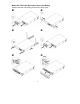
Mount the UPS in the Rack and Connect the Battery Attention: Install the rails following the instructions in the rail kit.
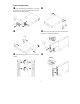
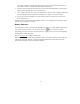
Tower Configuration Press and hold the black switch (see location designation on UPS) to the right while removing the power processing module. Snap the display bezel out the rear to begin rotation. Note: Place the UPS in the final operating location prior to module reinstallation.
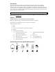
2: START UP Connect Equipment to the UPS Rear Panels 1500 VA, 120 V: 1500 VA, 230 V: 3000 VA, 120 V: 3000 VA, 230 V: Note: • The ‘outlet groups’ can be controlled through the network software. See Network Management Card documentation. • A laser printer draws significantly more power than other types of equipment and may overload the UPS.
The battery will charge to full capacity during the first few hours of normal operation. Do not expect full ‘on battery’ capability during this initial charge period. 2. After the UPS has ended the immediate self-test with online LED illumination, check the front display for any fault indicators (see Troubleshooting). 3. 120 V models: Check the site wiring fault LED located on the rear panel. It will be illuminated if the UPS is plugged into an improperly wired utility power outlet (see Troubleshooting).
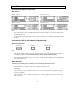
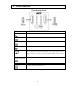
3: BASIC OPERATION Front Display Panel INDICATOR DESCRIPTION Online The UPS is supplying utility power to the connected equipment. AVR The UPS is compensating for either a high or low utility voltage. On Battery The UPS is supplying battery power to the connected equipment. Overload The connected loads are drawing more than the UPS power rating. Bypass The connected loads are being powered directly by the utility power connection and not through the power processing module.
FEATURE FUNCTION Self-Test Automatic: The UPS performs a self-test automatically when turned on, and every two weeks thereafter (by default). During the self-test, the UPS briefly operates the connected equipment on battery. Manual: Press and hold the test. Cold Start button for a few seconds to initiate the self- Supply battery power to the UPS and connected equipment in the absence of button for one second and utility voltage (see Troubleshooting). Press the release.
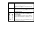
4: USER CONFIGURABLE ITEMS NOTE: SETTINGS ARE MADE THROUGH THE SUPPLIED POWERCHUTE SOFTWARE OR THE NETWORK INTERFACE CONNECTION. FACTORY DEFAULT FUNCTION REFER TO THE SOFTWARE HELP GUIDES FOR DETAILS. USER SELECTABLE CHOICES DESCRIPTION Automatic Self-Test Every 14 days (336 hours) Every 14 days (336 hours), Every 7 days (168 hours), On Startup Only, No Self-Test This function sets the interval at which the UPS will execute a self-test.
NOTE: SETTINGS ARE MADE THROUGH THE SUPPLIED POWERCHUTE SOFTWARE OR THE NETWORK INTERFACE CONNECTION. FUNCTION High Transfer Point Low Transfer Point FACTORY DEFAULT REFER TO THE SOFTWARE HELP GUIDES FOR DETAILS.
5: STORAGE, MAINTENANCE, SHIPPING, AND SERVICE Storage Store the UPS covered in a cool, dry location, with the battery fully charged. At -15 to +30 °C (+5 to +86 °F), charge the UPS battery every six months. At +30 to +45 °C (+86 to +113 °F), charge the UPS battery every three months. Battery Module Maintenance The UPS battery life differs based on usage and environment. Consider replacing the battery every three years. This UPS has an easy to replace, hot-swappable battery.
Shipping 1. Shut down and disconnect any equipment attached to the UPS. 2. Shut down the UPS, and disconnect the UPS from the utility power outlet. 3. Unplug the battery connector. For further shipping instructions and to obtain appropriate packing materials, contact APC (see Contact Information). Service If the UPS requires service do not return it to the dealer. Follow these steps: 1. 2. Review the problems discussed in Troubleshooting to eliminate common problems.
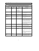
6: TROUBLESHOOTING Use the chart below to solve minor UPS installation and operation problems. Refer to APC for assistance with complex UPS problems. SOLUTION PROBLEM AND/OR POSSIBLE CAUSE UPS WILL NOT TURN ON UPS not connected to utility power supply. Check that the power cord from the UPS to the utility power supply is securely connected at both ends. Battery not connected properly. Check that the battery connector is fully snapped into position. Very low or no utility voltage.
PROBLEM AND/OR POSSIBLE CAUSE SOLUTION NOT ALL OUTLETS ARE POWERED One or more of the outlet groups (labeled ‘1’, ‘2’, and ‘3’) are shut off via the network interface connection. Access the UPS control panel via the network interface connection and check the status of the outlets. If the settings are not what are expected, change them accordingly and review security settings (password, etc.). 3000 VA, 120 V model only: One or more of the outlet groups are overloaded and the circuit breaker(s) tripped.
PROBLEM AND/OR POSSIBLE CAUSE SOLUTION THE OVERLOAD LED IS ILLUMINATED AND THE UPS EMITS A SUSTAINED ALARM TONE The UPS is overloaded. The connected equipment is drawing more VA or more Watts than the UPS can sustain. The connected equipment exceeds the specified “maximum load.” The alarm remains on until the overload is removed. Disconnect nonessential equipment from the UPS to eliminate the overload.
PROBLEM AND/OR POSSIBLE CAUSE SOLUTION THE BYPASS LED IS ILLUMINATED The UPS has briefly directed power around the power processing module during a startup sequence. Nothing. This is a normal behavior of the UPS during startup. The UPS has directed power around the power processing module because of an internal fault. Replace the power processing module (See Storage, Maintenance, Transporting, and Service). THERE IS NO UTILITY POWER There is no utility power and the UPS is off.
7: REGULATORY AND WARRANTY INFORMATION 120V models This equipment has been tested and found to comply with the limits for a Class A digital device, pursuant to part 15 of the FCC Rules. These limits are designed to provide reasonable protection against harmful interference when the equipment is operated in a commercial environment.
Limited Warranty American Power Conversion (APC) warrants its products to be free from defects in materials and workmanship for a period of two years from the date of purchase. Its obligation under this warranty is limited to repairing or replacing, at its own sole option, any such defective products. To obtain service under warranty you must obtain a Returned Material Authorization (RMA) number from customer support.