User Manual English APC Smart-UPS 2400/3000 VA 100/110-120 VAC 3U Tower/Rack Mount Uninterruptible Power Supply 990-2233A 02/2005
Introduction/Before Installation Introduction/Before Installation About this Manual The APC Smart-UPS® RT (SURTA2400XLJ/SURTA3000XL/SURTA3000XLTW) is a high-performance Uninterruptible Power Supply (UPS) designed to prevent blackouts, brownouts, sags and surges from reaching your computers, servers, and other sensitive electronic equipment. This manual describes procedures on how to properly unpack and install the UPS, connect the battery and equipment, configure accessories, and start up the system.
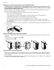
Installation Installation Refer to instructions below for information on how to install the UPS in a rack, in a tower configuration, or when installing the UPS with optional battery pack(s). Once the UPS has been placed in the desired tower or rack location, complete the remaining installation steps in sequential order, beginning with “Connect Equipment to the UPS” on page 4.
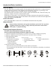
Installation Connectors Type Description 120V/3000 VA PDU Receptacles Connect equipment to the Power Distribution Unit (PDU) receptacles on the rear of the UPS. 100V/2400 VA PDU Receptacles Connect equipment to the Power Distribution Unit (PDU) receptacles on the rear of the UPS. 110-120 V 3000 VA PDU Receptacles Connect equipment to the Power Distribution Unit (PDU) receptacles on the rear of the UPS.
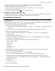
Installation If Required, Connect the Emergency Power Off (EPO) Feature The EPO interface is a safety extra low voltage (SELV) circuit. Connect it only to other SELV circuits. To avoid damage to the UPS, do not connect the EPO interface to any circuit other than a closure type circuit, properly isolated from the utility. The EPO feature provides immediate de-energizing of the UPS and connected equipment from a remote location, without switching to battery operation. 1.
Terminal Mode Configuration Avoid using extension cords when connecting equipment to and from the UPS. 1. 2. 3. 4. Ensure that equipment is connected to the UPS. Only use a power cord to plug the UPS into a two-pole three-wire grounded receptable. Turn on all connected equipment. To power up the UPS, press the button on the front panel. For Additional Computer System Security For additional computer system security, install PowerChute® Business Edition Smart-UPS® monitoring software.
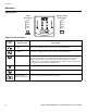
Operation Operation Display Panel Load Percentages Battery Charge Percentages 96% 72% 48% 24% 0% 85% 68% 51% 34% 17% Display Panel Indicators Indicator LED 8 Indicator Title Description On Line The UPS is supplying utility power to the connected equipment. On Battery The UPS is supplying battery power to the connected equipment. Bypass The Bypass LED illuminates indicating that the UPS is in bypass mode. Utility power is sent directly to connected equipment during bypass mode operation.
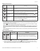
Operation Display Panel Functions Feature Button Feature Title Function Power On Press this button to turn on the UPS. Continue reading for additional capabilities. Power Off Press this button to turn off the UPS output. NOTE: The battery will continue to charge and the fans will continue to run while the UPS is connected to the utility. Cold Start When there is no utility power and the UPS is off, press and hold the button to power up the UPS and connected equipment.
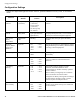
Configuration Settings Configuration Settings Settings are adjusted through PowerChute software, optional SmartSlot accessory cards, or in terminal mode. Function Factory Default User Selectable Choices Description Automatic Self-Test Every 14 days (336 hours) • Every 7 days (168 hours) • Every 14 days (336 hours) • On start up only • No self-test Set the interval at which the UPS will execute a self-test. UPS ID UPS_IDEN Up to eight characters (alphanumeric) Uniquely identify the UPS, (i.e.
Configuration Settings Factory Default Function User Selectable Choices Description High Bypass Points 100V Models: 110V 120V Models: 133V • • • • • • • • 100V 107V 110V 113V 116V 119V 122V 125V 128V 110-120V • 127V • 130V • 133V • 136V • 139V • 142V • 145V • 148V Maximum voltage that the UPS will pass to connected equipment during internal bypass operation.
Storage, Maintenance, Transport, and Service Storage, Maintenance, Transport, and Service Storage Store the UPS covered in a cool, dry location with the battery(s) fully charged. At 5° to 113° F (–15° to 45° C), charge the UPS battery every six months. To Install a Replacement Battery This UPS has an easy-to-replace, hot-swappable battery module. Replacement is a safe procedure, isolated from electrical hazards. You may leave the UPS and connected equipment on during the replacement procedure.
Storage, Maintenance, Transport, and Service Smart-UPS RT 2400/3000 VA Tower/Rack-Mount UPS User Manual 13
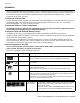
Storage, Maintenance, Transport, and Service 1. Install the replacement battery modules in the UPS. a. Install the bottom and top battery modules. b. Connect the battery modules . c. Push in the battery connectors . d. Lift up the battery cover and install the screws . e. Install the front bezel !. ! Transporting the UPS to Another Location Always DISCONNECT the Battery(s) before shipping to be in compliance with U.S. Department of Transportation (DOT) regulations.
Troubleshooting Service Always DISCONNECT THE BATTERY before shipping the UPS to be in compliance with U.S. Department of Transportation (DOT) regulations. If the UPS requires service do not return it to the dealer. Follow these steps: 1. Review the problems discussed in “Troubleshooting” to eliminate common problems. 2. If the problem persists, contact APC Customer Service through the APC Web site, www.apc.com. – Note the model number of the UPS, the serial number, and the date purchased.
Troubleshooting Problem and/or Possible Cause Normal UPS operation when running On Battery. Solution None: The UPS is protecting the connected equipment. Press the button to silence this alarm. UPS is not providing expected backup time The UPS battery is weak due to a recent power outage or battery is near the end of its service life. Charge the battery. Batteries require recharging after extended outages. Batteries can wear faster when put into service often or when operated at elevated temperatures.
Troubleshooting Problem and/or Possible Cause Solution Fault and Overload LEDs illuminated and UPS emits a sustained alarm tone (Refer to “Display Panel Indicators” on page 8.) The UPS has ceased sending power to connected equipment. The connected equipment exceeds the specified “maximum load” as defined in Specifications on the APC Web site, www.apc.com. Disconnect nonessential equipment from the UPS to eliminate the overload condition.
Radio Frequency, Regulatory, Warranty, and Copyright Information Problem and/or Possible Cause There is no LED illumination. Solution The line voltage is extremely low and should be checked by an electrician. On Line LED (Refer to “Display Panel Indicators” on page 8.) There is no LED illumination. The UPS is running On Battery, or it must be turned on. The LED is blinking. The UPS is running an internal self-test.
Radio Frequency, Regulatory, Warranty, and Copyright Information Limited Warranty American Power Conversion (APC) warrants its products to be free from defects in materials and workmanship for a period of two years from the date of purchase. Its obligation under this warranty is limited to repairing or replacing, at its own sole option, any such defective products. To obtain service under warranty you must obtain a Returned Material Authorization (RMA) number from customer support.