Operation Manual Smart-UPS C ® Uninterruptible Power Supply 1000/1500 VA Tower 120 Vac
This manual is available in English on the enclosed CD. Este manual está disponible en español en el CD-ROM adjunto. Ce manuel est disponible en français sur le CD-ROM ci-inclus.
Product Description The APC® by Schneider Electric Smart-UPS® 1000/1500 VA Tower is a high performance uninterruptible power supply (UPS). It provides protection for electronic equipment from utility power blackouts, brownouts, sags, and surges, small utility fluctuations and large disturbances. The UPS also provides battery backup power for connected equipment until utility power returns to safe levels or the batteries are fully discharged.
Product Overview Front panel features 1 Display interface su0453b 2 Bezel 3 Battery 4 Internal battery connector Rear panel features 1 USB Port 2 Serial data port 3 Battery connector 4 Circuit breaker 5 UPS input 6 Outlets su0325d 7 Ground screw Installation For UPS installation information, refer to the Smart-UPS Installation Guide 1000/1500 VA 120 Vac Tower, that is included with the UPS.
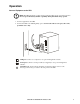
Operation Connect Equipment to the UPS Note: The UPS will charge to 90% capacity in the first three hours of normal operation. Do not expect full battery runtime capability during this initial charge period. 1. Connect equipment to the UPS. su0441b 2. Connect the UPS to the building utility power. Connect the UPS to a two-pole, three-wire, grounded source only. USB port: Connect to a computer to use power management software.
Power-Saving LCD Screen The display interface can be configured to remain continuously illuminated or to extinguish after a period of inactivity to save electricity. 1. Continuous Illumination mode: Press and hold the DISPLAY button for two seconds. The display will illuminate and the UPS will beep to confirm Continuous Illumination mode is activated. 2. Power-Saving mode: Press and hold the DISPLAY button for two seconds.
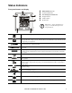
Status Indicators su0740b Front panel buttons and display 1 Online/On Battery LED 2 POWER ON/OFF button 3 Site Wiring/System Fault LED 4 Display interface 5 DISPLAY button 6 MUTE button Note: Refer to “Feature Quick-Reference” on page 7 for a detailed description of the front panel buttons. On Line: The UPS is supplying conditioned utility power to connected equipment.
LED status indicators Status Power On The UPS is supplying utility power to connected equipment. LED Audible Indicator Terminates Audible Indicator On The Online LED illuminates green. None N/A On Battery The Online LED illuminates The UPS is supplying battery power amber. from the internal battery pack. The UPS beeps 4 times every 30 seconds. The beeping stops when utility power is restored or the MUTE button is pressed for 2 seconds. System Fault The UPS detects an internal system fault.
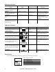
Feature Quick-Reference Function Button Timing UPS (seconds) Status Description Power POWER ON 0.2 Off Press the POWER ON/OFF button to turn on the UPS and operate on utility power. If utility input power is not available the UPS will operate on battery power. 2 On Press the POWER ON/OFF button to turn off the UPS. Status Inquiry 0.2 On Verify the status or condition of the UPS. The LCD will illuminate for 60 seconds.
Troubleshooting Problem and Possible Cause Solution The UPS will not turn on or there is no output. The unit has not been turned on. Press the POWER button once to turn on the UPS. The UPS is not connected to utility power. Be sure the power cable is securely connected to the unit and to the utility power supply. The input circuit breaker has tripped. Reduce the load on the UPS. Disconnect nonessential equipment and reset the circuit breaker. The unit shows very low or no input utility voltage.
Service If the unit requires service, do not return it to the dealer. Follow these steps: 1. Review the Troubleshooting section of the manual to eliminate common problems. 2. If the problem persists, contact APC Customer Support through the APC Web site, www.apc.com. a. Note the model number and serial number and the date of purchase. The model and serial numbers are located on the rear panel of the unit and are available through the LCD display on select models. b.
Two-Year Factory Warranty This warranty applies only to the products you purchase for your use in accordance with this manual. Terms of warranty APC warrants its products to be free from defects in materials and workmanship for a period of two years from the date of purchase. APC will repair or replace defective products covered by this warranty. This warranty does not apply to equipment that has been damaged by accident, negligence or misapplication or has been altered or modified in any way.
APC Worldwide Customer Support Customer support for this or any other APC product is available at no charge in any of the following ways: • Visit the APC Web site to access documents in the APC Knowledge Base and to submit customer support requests. – www.apc.com (Corporate Headquarters) Connect to localized APC Web sites for specific countries, each of which provides customer support information. – www.apc.com/support/ Global support searching APC Knowledge Base and using e-support.