Operation Manual Smart-UPS® X-Series UPS 750 VA 1000 VA 1500 VA 120V 230V
Overview........................................................................... 1 About the UPS . . . . . . . . . . . . . . . . . . . . . . . . . . . . . . . . . . . . . . . . . . . .1 Safety . . . . . . . . . . . . . . . . . . . . . . . . . . . . . . . . . . . . . . . . . . . . . . . . . . .1 Product Overview . . . . . . . . . . . . . . . . . . . . . . . . . . . . . . . . . . . . . . . . .1 Front panel . . . . . . . . . . . . . . . . . . . . . . . . . . . . . . . . . . . . . . . . . . . . . .
Emergency Power Off . . . . . . . . . . . . . . . . . . . . . . . . . . . . . . . . . . . . 12 EPO Overview . . . . . . . . . . . . . . . . . . . . . . . . . . . . . . . . . . . . . . . . . . 12 Normally open contacts . . . . . . . . . . . . . . . . . . . . . . . . . . . . . . . . . . 12 Normally closed contacts . . . . . . . . . . . . . . . . . . . . . . . . . . . . . . . . . 12 Troubleshooting ............................................................ 13 Service and Support.............................
Overview About the UPS The APC® by Schneider Electric Smart-UPS® X-Series is a high performance uninterruptible power supply (UPS). It provides protection for electronic equipment from utility power blackouts, brownouts, sags, and surges; small utility fluctuations and large disturbances. The UPS also provides battery backup power until utility power returns to safe levels or the batteries are fully discharged. Safety Read the Safety Guide included in the package before installing the UPS.
su0341a 230 V 2 Smart-UPS X-Series Operation
Specifications Operating Conditions This unit is intended for indoor use only. Select a location sturdy enough to support the weight of the UPS and External Battery Packs (XLBP).. Do not operate the unit where there is excessive dust, or the temperature or humidity are outside the specified limits. This unit has front and rear air vents. Allow adequate space for proper ventilation. Environmental Specifications Environmental factors impact battery life.
Operation Connect Equipment to the UPS Note: The UPS will charge to 90% capacity in the first three hours of normal operation. Do not expect full battery runtime capability during this initial charge period. 1. Connect equipment to the outlets on the rear panel of the UPS. 2. Connect the UPS to the building utility power. Connect the UPS to a two-pole, three-wire, grounded source only. 3. Press the ON/OFF button on the front panel of the UPS to power the unit and all connected equipment. 4.
TVSS Ground Screw: The UPS features a Transient Voltage Surge-Suppression (TVSS) screw for connecting the ground lead on surge suppression devices such as a telephone and network line protectors. When connecting a grounding cable, disconnect the UPS from utility power.
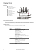
Display Panel Overview Online indicator UPS Output On/Off button On Battery indicator Fault indicator Replace Battery indicator Display screen UP and DOWN buttons ENTER button su0343a ESCAPE button APC By Schneider Electric Using the display interface Use the UP and DOWN buttons to scroll through the main menu options. Press ENTER to view the submenus under each main menu option. Press ESCAPE to exit a sub-menu and return to a main menu.
Menu General Functions About Display information about this unit: • Unit model number • Serial number • Battery information •Model number •Installation date •Suggested battery replacement date •UPS firmware version Advanced menus The Advanced menus provide additional options for the UPS and are available only if the display interface is configured to use the Advanced menus.
Configuration UPS Settings Start-up Settings Configure these settings at initial start-up, using the display interface or APC PowerChute® software. Note: During start-up, use the display interface to configure these settings. If nothing is selected, the unit will use the default settings. Function Factory Default Options Description Language English • English • French* • German* • Spanish* • Italian* • Portuguese* The language for the display interface.
Function Factory Default Options Description Nominal Output 230 V: 230 VAC Voltage 120 V: 120 VAC 230 V: 220, 230, 240 Set the nominal output voltage of the UPS on VAC battery. This is available on 230 V models 120 V: N/A only. Transfer Sensitivity High, Low, Medium High Select the level of sensitivity to power events that the UPS will tolerate. • High: The UPS will go on battery power more often to provide the cleanest power supply to the connected equipment.
Controllable Outlet Groups Overview The rear panel of the UPS has multiple outlets, some are grouped into Controllable Outlet Groups, all of the other outlets are the UPS outlets, which function as an outlet group. All of these groups can independently turn off, turn on, shut down, and reboot connected equipment.
su0437a su0435a Smart-UPS X-Series Operation su0487a su0488a 1500 VA, 120 V and 230 V.
Connect all critical equipment to the same outlet group.) 2. Connect peripheral equipment to the Controllable Outlet Groups.
Function Factory Default Options Description Load Shed On Runtime Disabled When the battery runtime falls below the specified value, the Controllable Outlet Group will turn off. • Shutdown with delay • Shutdown immediately • Turn off immediately • Turn off with delay • Disabled Configure this time using the LOAD SHED RUNTIME REMAINING setting.
Emergency Power Off Overview The Emergency Power Off (EPO) option is a safety feature that will immediately disconnect all connected equipment from utility power. The UPS will immediately shut down and will not switch to battery power. Connect each UPS to the EPO switch, even if the UPS units are used in parallel. The UPS must be restarted for power to return to connected equipment. Press the ON/OFF button on the front panel of the UPS. 1.
accordance with national and local regulations. Troubleshooting Problem and Possible Cause Solution The UPS will not turn on or there is no output The unit has not been turned on. Press the ON button once to turn on the UPS. The UPS is not connected to utility power. Be sure that the power cable is securely connected to the unit and to the utility power supply. The input circuit breaker has tripped. Reduce the load to the UPS, disconnect nonessential equipment and reset the circuit breaker.
Problem and Possible Cause Solution All indicators are illuminated and the UPS is plugged into a wall outlet The UPS has shut down and the battery has discharged from an extended outage. None. The UPS will return to normal operation when the power is restored and the battery has a sufficient charge. The replace battery indicator is illuminated The battery has a weak charge. Allow the battery to recharge for at least four hours. Then, perform a self-test.
Service and Support Service If the unit requires service, do not return it to the dealer. Follow these steps: 1. Review the Troubleshooting section of the manual to eliminate common problems. 2. If the problem persists, contact APC Customer Support through the APC Web site, www.apc.com. a. Note the model number and serial number and the date of purchase. The model and serial numbers are located on the rear panel of the unit and are available through the LCD display on select models. b.
APC Worldwide Customer Support Customer support for this or any other APC product is available at no charge in any of the following ways: • Visit the APC Web site to access documents in the APC Knowledge Base and to submit customer support requests. – www.apc.com (Corporate Headquarters) Connect to localized APC Web sites for specific countries, each of which provides customer support information. – www.apc.com/support/ Global support searching APC Knowledge Base and using e-support.
Smart-UPS Factory Warranty LIMITED WARRANTY American Power Conversion (APC) warrants its Smart-UPS (Products) to be free from defects in materials and workmanship for a period of three (3) years, excluding the batteries, which are warranted for two (2) years from date of purchase. APC's obligation under this warranty is limited to repairing or replacing, at its own sole option, any such defective products.
20 Smart-UPS X-Series Operation
EC Declaration of Conformity 2009 Date of product declaration Harmonized Standards EN60950-1; IEC60950-1; EN62040-1-1; EN55022; EN55024; IEC61000-3-2, 3-3, 4-2, 4-3, 4-4, 4-5, 4-6, 4-11 Applicable Council Directives 2006/95/EC; 2004/108/EC Type of Equipment Uninterruptible Power Supply Model Numbers SMX750I, SMX1000I, SMX1500RMI2U, SMX1500RMI2UNC Manufacturers American Power Conversion 132 Fairgrounds Rd West Kingston, RI 02892 USA American Power Conversion 2nd Street, PEZA Cavite Economic Zone R
© 2011 APC by Schneider Electric. APC, the APC logo are owned by Schneider Electric Industries S.A.S., American Power Conversion Corporation, or their affiliated companies. All other trademarks are property of their respective owners.