Operation Manual Smart-UPS™ C Uninterruptible Power Supply 1000/1500 VA Tower / Rack-Mount 2U 120 Vac/230 Vac su10 1 2a
Important Safety Messages SAVE THESE INSTRUCTIONS - This manual contains important instructions that should be followed during installation and maintenance of the UPS and batteries. Read the instructions carefully. Become familiar with the device before trying to install, operate, service or maintain it. The following special messages may appear throughout this document or on the equipment to warn of potential hazards or to call attention to information that clarifies or simplifies a procedure.
Safety and General Information Inspect the package contents upon receipt. Notify the carrier and dealer if there is any damage. • Adhere to all national and local electrical codes. • All wiring must be performed by a qualified electrician. • Changes and modifications to this unit not expressly approved by APC by Schneider Electric could void the warranty. • This UPS is intended for indoor use only.
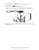
Hardwire safety • Check that all branch circuit (mains) and low voltage (control) circuits are deenergized, and locked out before installing cables or making connections, whether in the junction box or to the UPS. • Wiring by a qualified electrician is required. • Check national and local codes before wiring. • Strain relief is required for all hardwiring (supplied with select products). Snap in type strain reliefs are recommended. • All openings that allow access to UPS hardwire terminals must be covered.
SMC1000-2UC and SMC1000I-2UC Rack-Mount SMC1000C, SMC1000IC, SMC1500C and SMC1500IC Tower su0 9 97a SMC1500-2UC and SMC1500I-2UC Rack-Mount Specifications For additional specifications, refer to the APC Web site at www.apc.com.
Product Overview Front panel features = SMC1000-2UC and SMC1000I-2UC Rack-Mount SMC1000C, SMC1000IC, SMC1500C, and SMC1500ICTower 93a su0994a su0 9 SMC1500-2UC and SMC1500I-2UC Rack-Mount Display (more information below) su 09 92 Bezel a Battery Internal battery connector Rear panel features APC™ SmartConnect port Serial port USB port Chassis ground screw Circuit breaker/overload protection Outlets Battery connector SMC1000-2UC Rack-Mount LINK/ACT NE TWORK su0960a Sma
SMC1500-2UC Rack-Mount SMC1000C and SMC1500C Tower LINK/ACT LINK/ACT NE TWO RK NE TWO RK su0961a SMC1000I-2UC Rack-Mount su0959a su0960b SMC1000IC and SMC1500IC Tower SMC1500I-2UC Rack-Mount su0960c su0959b Dimensions and weights Tower Models Rack-Mount Models D D H H s u09 s u09 6 65b 64b W Smart-UPS C 1000/1500 VA 120/230 Vac Tower / Rack-Mount 2U W
Model SMC1000C, SMC1000IC SMC1500C, SMC1500IC Dimensions (in/mm) H x W x D Weight (lb / kg) 8.6 x 6.7 x 17.3 in (219 x 171 x 439 mm) 37.5 / 17 44.3 / 20.1 SMC1000-2UC, SMC1000I-2UC 3.4 x 17 x 16 in (86 x 432 x 409 mm) 39.3 / 17.8 SMC1500-2UC, SMC1500I-2UC 3.4 x 17 x 18.8 in (86 x 432 x 477 mm) 55.8 / 25.3 Installation For UPS installation information, refer to the Installation Guide included with the UPS.
1. Connect equipment to the outlets in the rear of the UPS. 2. Connect the APC SmartConnect port to your nearest network switch using the cable provided. 3. Connect the UPS input to AC power. 4. Press the main power button on the UPS display to turn on the UPS output. Note: The On-line LED will light green when the output is on. 5. Log onto www.smartconnect.apc.com or scan the QR code to launch the registration process.
Status Indicators Display panel features 1000/1500 VA 230 Vac su0740c su0740d 1000/1500 VA 120 Vac On Line/On Battery LED Display interface POWER ON/OFF button MENU button Site Wiring Fault/System Error LED MUTE/ENTER button Note: Refer to “Display Menu” section on page 11 in this manual for a detailed description of the front panel buttons and icons. Status LED Power On The UPS is supplying AC power to connected equipment.
0 Vac 230 Vac Description Overload: The equipment connected to the UPS is drawing more power than the UPS rating allows. Event: The event counter indicates the number of events that occurred to cause the UPS to switch to battery operation. In: Input voltage. Out: Output voltage. Load: Output power. System Error Detected: An internal system error has occurred. The error number will illuminate on the display. Refer to “System Errors and Message Codes” section on page 15.
Status LCD Icon System Error Detected The UPS has experienced an internal error. Audible Alarms 120 Vac models N/A 230 Vac models Audible Alarm Terminates Identify the error message on the display and refer to the table of codes under “System Errors and Message Codes” section on page 15. Display Menu The main part of the display will show different parameters of the UPS.
Function Options Firmware Upgrade Description • UP.0 This mode only appears when firmware is stored in UP.0 = firmware valid and different memory, and different from the current firmware running. from current running firmware UP.0 indicates new firmware is available and different from current firmware, but will not install until instructed by user. • UP.1 UP.1 = confirm the firmware update Pressing MUTE instructs the UPS to install new firmware, and changes the display to UP.1. UP.
Function Options Description • for 120V models: 110 -> 120 -> 127 • for 230V models: 220 -> 230 -> 240 Output Voltage Setting LCD Energy Save Mode Communication Protocol Select the output voltage (not available on some models) dP.1 - Enabled (Default) - When enabled the LCD will automatically dim after 60 seconds of no activity • dP.0 = disable • dP.1 = enable dP.0 - Disabled - The display will stay illuminated indefinitely. • cP.0 = disable • cP.
Function Options Description Displays the 14-character SmartConnect Product Key in 4 parts each time Mute is pressed. To see the characters, press MENU to toggle through the groups. The groups are displayed with decimal point movement to ease knowing which part of the code is being displayed. SmartConnect Product Key Example: Cod -> 123 -> -> 0.1.2 -> -> 4.56-> -> 78.9 -> -> 34 Troubleshooting Problem and Possible Cause Solution The UPS will not turn on or there is no output.
Problem and Possible Cause Solution The UPS displays a site wiring error message (Error code G.00). Wiring errors detected include missing Ground, Hot- System Error LED will flash on 2 seconds and flash off 1 second Neutral polarity reversal, and overloaded Neutral. to indicate site wiring fault. If the UPS indicates a site wiring error, have a qualified electrician inspect the building wiring. (Applicable for 120 V units only.) Battery lifetimestatus (Error code L.01/L.
Battery Replacement Always recycle used batteries. For information on recycling a used battery, refer to the Battery Disposal Information sheet included with the replacement battery. Battery life is highly dependent on temperature and use. To identify when to replace batteries, the Smart-UPS models have a predictive battery replacement date indication and automatic (and configurable) self-tests. Proactively replace batteries to maintain the highest availability.
Limited Factory Warranty Schneider Electric IT Corporation (SEIT), warrants its products to be free from defects in materials and workmanship for a period of two (2) years from the date of purchase. The SEIT obligation under this warranty is limited to repairing or replacing, at its own sole option, any such defective products. Repair or replacement of a defective product or parts thereof does not extend the original warranty period.
18 Smart-UPS C 1000/1500 VA 120/230 Vac Tower / Rack-Mount 2U
APC by Schneider Electric Worldwide Customer Support Customer support for this or any other APC by Schneider Electric product is available at no charge in any of the following ways: • Visit the APC by Schneider Electric web site to access documents in the APC by Schneider Electric Knowledge Base and to submit customer support requests. – www.apc.com (Corporate Headquarters) Connect to localized APC by Schneider Electric web sites for specific countries, each of which provides customer support information.