Redundant Switch User’s Manual Notice: In case of a problem with this product, do not return to the place of purchase. Go to the support page at www.apcc.com for Technical Support or call 1-800-800-4272 for prompt customer service.
Entire contents copyright ©1999 by American Power Conversion. All rights reserved. Reproduction in whole or in part without permission is prohibited. Smart-UPS is a registered trademark of APC. All other trademarks are the property of their respective owners.
English Redundant Switch User’s Manual 990-0253A, Revision 2 6/99
Table of Contents Safety ................................................................................................................................................................................................ 1 Initial Startup ..................................................................................................................................................................................... 2 Installation ...............................................................................
Safety This section contains important instructions that should be followed during installation and maintenance of the Redundant Switch. It is intended for customers who setup, install, relocate, or maintain APC equipment. Electrical Safety • Do not work alone under hazardous conditions. • High short circuit current through conductive materials could cause severe burns. • Check that the power cord(s), plug(s), and sockets are in good condition.
Initial Startup Reminder! To obtain warranty coverage, please fill out and return the warranty registration card now. Inspection Inspect the Redundant Switch upon receipt. Notify the carrier and dealer if there is damage. The packaging is recyclable; save it for reuse or dispose of it properly. Unpacking The Redundant Switch package contains the Redundant Switch unit, its bag of hardware (OM8500), 1U mounting rails, and its bag of mounting hardware (OM-7600).
1. Install Redundant Switch. •Before plugging in the unit, install any compatible SmartSlot accessory (check our website at www.apcc.com). Follow the installation instructions that come with the accessory. Notes: 1. This Redundant Switch is equipped with a SmartSlot for additional manageability. See the APC Website (www.apcc.com) for information on plug-in accessories. 2. SNMP accessories are currently unsupported in the Redundant Switch SmartSlot.
Install the Rails Note: The mounting rails are only necessary if you are using a four-post rack. If you are using a two-post rack the Redundant Switch will be mounted by the ears alone. Skip to Connect and Route the Cables. Two rails and associated hardware are included with the Redundant Switch. For information on which clips and screws the rack you are using requires, see Appendix A: Rack Mount Supplement. Prepare the rack’s rail-holes to mount the Redundant Switch’s ears and rails as appropriate.
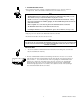
Mount the Redundant Switch in the Rack Note: Two people should perform this step. 1. Position the Redundant Switch forward of the mounted rear rail segments. 2. Align the front and rear rail segments and slide the front segment onto the rear segment. 3. Align the Redundant Switch ears with the front rack rails and use rack hardware to secure the mounting ears to the rack rails. 4. From the rear of the rack, insert and tighten the slide screws and nuts. 2. Connect Equipment.
Supported Configurations Two supported connection configurations for Redundant Switch are illustrated below. For detailed information on these configurations and other supported configurations, please visit the APC Website at http://www.apcc.com. Notes: • Redundant Switch does not support communications with accessories installed in the UPS, except for SNMP accessories. Install any other accessory you need in Redundant Switch. • Both UPS units should be the same sine-wave model.
Operating Instructions Front View Status Status Select Select To UPS B Level R T N I + N 2 4 AC Source A B To UPS A To Server Function Bright Source selected EPO Dim Emergency Power Off Off Source OK, but not selected Source not OK Redundant Switch Note: Only the Factory Default settings shown below should be used. Check that these are the current settings for your unit. Additional setting are for future upgrades.
Troubleshooting Redundant Switch Note: Only APC Support Personnel should open the Redundant Switch for repair. Problem Possible Cause Redundant Switch will not turn on. Very low or no utility voltage. Corrective Action Check the AC power supply to the Redundant Switch with a table lamp. If very dim, have the utility voltage checked. Check that AC plugs are properly connected between Redundant Switch and the UPSs. Server cannot communicate with attached UPS through Redundant Switch.
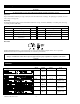
Specifications SU041, SU042-1, SU042-2 SU045-1 SU043, SU044 Acceptable input voltage 120 VAC: 0 - 165 VAC 208 VAC: 0 - 275 VAC 230 VAC: 0 - 325 VAC Output voltage (by default when used with Smart-UPS) 120 VAC: 108 - 132 VAC 208 VAC: 187 - 229 VAC 230 VAC: 207 - 253 VAC Frequency limits (on-line operation) 47 -63 Hz.
Service If the UPS requires service do not return it to the dealer! Follow these steps: 1. Use the Troubleshooting sections of this manual and the UPS User’s Manual to eliminate common problems. 2. Verify that no circuit breakers are tripped. A tripped circuit breaker is the most common problem! 3. If the problem persists, call customer service or visit the APC Internet Website (www.apcc.com). 4. Note the model numbers and serial numbers of the UPSs and the Redundant Switch and the date(s) purchased.
Appendix A: Rack Mount Supplement Installation Tips for Rack Mount Units Please observe the following items when installing the Rack Mount Redundant Switch: •The Redundant switch is furnished with brackets for mounting in standard 19” (46.5 cm) rack mount brackets. •Select a rack location with adequate air flow that is free from excessive dust. Do not operate the Redundant Switch where temperature or humidity are outside the limits listed under Specifications.