Redundant Switch - Applications Guide March 22, 1999 Redundant Switch Applications Guide 1
Redundant Switch - Applications Guide March 22, 1999 This Applications Guide contains configuration information for the following using Redundant Switch in the following applications: Application #1 - Redundant Smart-UPS System Application #2 - Redundant Smart-UPS System with Extended Runtime Application #3 - Redundant Smart-UPS System with generator Application #4 - Phase Redundant Single Smart-UPS System Application #5 - Phase Redundancy and UPS Redundancy to Microsoft Cluster Server peripheral equipmen
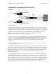
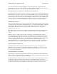
Redundant Switch - Applications Guide March 22, 1999 Application #1 - Redundant Smart-UPS System Configuration Smart-UPS "A" communications AC - phase 1 A Power to Redundant Switch Status Status Select Select Level R T N I + N 2 4 To UPS B AC Source B A To UPS A To Server Power to Load Function Bright Source selected EPO Emergency Power Off Dim Source OK, but not selected Off Source not OK Redundant Switch B B AC - phase 1 or independent phase (phase 2) Redundant Switch A communic
Redundant Switch - Applications Guide March 22, 1999 Redundant Switch Function Settings Use the factory preset settings (defaults). Smart-UPS Settings Follow the information given in the Smart-UPS User’s Manual to select the correct Smart-UPS configuration for the power environment. Follow the Redundant Switch PowerChute plus Configuration Procedure in the Redundant Switch User’s Manual if you plan to protect a server running a supported operating system with this Redundant Smart-UPS system.
Redundant Switch - Applications Guide March 22, 1999 safe server shutdown) to the standard availability power protection afforded by a single Smart-UPS. PowerChute plus records the event of switching to Source B as Self Test Failed: Invalid Test. Examine the Redundant Switch front panel or the front panels of the Smart-UPS units for details. MONITORING THE AVAILABILITY OF THE REDUNDANT SMART-UPS Redundant Switch continuously monitors the power delivery capability of the redundant Smart-UPS.
Redundant Switch - Applications Guide March 22, 1999 SWITCHING FROM PREFERRED SOURCE TO REDUNDANT SOURCE Redundant Switch switches load delivery to the redundant Smart-UPS when it detects that the power feed from Source A is unable to deliver power to the load. In this case, the availability of the system drops from very high (with both Smart-UPS available to provide AC power and battery back up) to the standard availability power protection afforded by a single Smart-UPS.
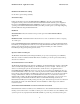
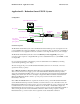
Redundant Switch - Applications Guide March 22, 1999 Application #2 - Redundant Smart-UPS XL System Configuration Smart-UPS XL Battery Pack(s) communications AC - phase 1 Smart-UPS XL "A" A Power to Redundant Switch Smart-UPS XL "B" AC - phase 1 or independent phase (phase 2) Redundant Switch A Status Status Select Select Level R T N I + N 2 4 To UPS B AC Source A B To UPS A To Server Power to Load Function Bright Source selected EPO Emergency Power Off B Dim Source OK, but not selecte
Redundant Switch - Applications Guide March 22, 1999 Redundant Switch Function Settings Use the factory preset settings (defaults). Smart-UPS Settings: Follow the information given in the Smart-UPS User’s Manual to select the correct Smart-UPS configuration for the power environment. Follow the Redundant Switch PowerChute plus Configuration Procedure in the Redundant Switch User’s Manual if you plan to protect a server running a supported operating system with this Redundant Smart-UPS system.
Redundant Switch - Applications Guide March 22, 1999 power, battery back up, and safe server shutdown functionality through the other Smart-UPS unit. Visit the installation to further diagnose the situation / restore the System, SWITCHING FROM PREFERRED SOURCE TO REDUNDANT SOURCE Redundant Switch switches load delivery and communications to the redundant Smart-UPS when it detects that the power feed from Source A is unable to deliver power to the load.
Redundant Switch - Applications Guide March 22, 1999 MONITORING HIGH AVAILABILITY Redundant Switch of the Redundant Smart-UPS System checks the availability of both Smart-UPS units to deliver power to the load. You can view the availability of both UPS-A and UPS-B at the Redundant Switch front panel (refer to the Redundant Switch User’s Manual- part number). The Smart-UPS units are preset to self-test every two weeks.
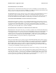
Redundant Switch - Applications Guide March 22, 1999 Application #3 - Redundant Smart-UPS System with generator Configuration Smart-UPS "A" AC - phase 1 Redundant Switch 1 A Status Status Select Select To UPS B Level R T N I + N 2 4 A AC Source B A To UPS A To Server Function Bright Source selected EPO Emergency Power Off communications Dim Source OK, but not selected Off Source not OK Redundant Switch Power to Redundant Switch 2 B AC - generator Status Status Select Select Lev
Redundant Switch - Applications Guide March 22, 1999 Smart-UPS Settings Follow the information given in the Smart-UPS User’s Manual to select the correct Smart-UPS configuration for the power environment. Follow the Redundant Switch PowerChute plus Configuration Procedure in the Redundant Switch User’s Manual if you plan to protect a server running a supported operating system with this Redundant Smart-UPS system. This procedure guides you through configuring the Smart-UPS units using Redundant Switch.
Redundant Switch - Applications Guide March 22, 1999 MONITORING THE AVAILABILITY OF THE REDUNDANT SMART-UPS Redundant Switch continuously monitors the power delivery capability of the redundant Smart-UPS. When Redundant Switch senses that its power feed from Source B is unable to deliver power to the load (if it were to be engaged) PowerChute plus records the event as Self Test Failed: Invalid Test, or as Alternate UPS engaged or Lost Comm.
Redundant Switch - Applications Guide March 22, 1999 SWITCHING FROM PREFERRED SOURCE TO REDUNDANT SOURCE Redundant Switch switches load delivery to the redundant Smart-UPS when it detects that the power feed from Source A is unable to deliver power to the load. In this case, the availability of the system drops from very high (with both Smart-UPS available to provide AC power and battery back up) to the standard availability power protection afforded by a single Smart-UPS.
Redundant Switch - Applications Guide March 22, 1999 Application #4 - Phase Redundant Single Smart-UPS System Configuration AC - phase 1 Redundant Switch A Power to Red Sw Status Status Select Select Level R T N I + N 2 4 To UPS B AC Source A B To UPS A To Server Power to Smart-UPS communications Function Bright Source selected EPO Emergency Power Off Dim Source OK, but not selected Off Source not OK Redundant Switch Power to Load B AC - phase 2 Goals and objectives Redundant Swit
Redundant Switch - Applications Guide March 22, 1999 Redundant Switch Function Settings Change the factory preset settings as shown in bold. Function Source Preference Setting Source A Source A Sensitivity and Source B Sensitivity Normal Source A transfer voltage and Source B transfer voltage Normal Description The Redundant Switch delivers power to the loads through input power connected to Source A.
Redundant Switch - Applications Guide March 22, 1999 Accessories Plug any Smart-UPS accessory into the Smart-UPS unit SmartSlot and not into Redundant Switch SmartSlot. The Smart-UPS SmartSlot supports each of the SmartSlot accessories.
Redundant Switch - Applications Guide March 22, 1999 Application #5: Phase Redundancy and UPS Redundancy to Microsoft Cluster Server peripheral equipment Not Yet Available 18
Redundant Switch - Applications Guide March 22, 1999 Application #6.
Redundant Switch - Applications Guide March 22, 1999 Accessories The Smart-UPS units support APC’s SmartSlot accessories in this application. Do not use SmartSlot accessories in the Redundant Switch SmartSlot. Redundant Switch does not communicate with the SmartUPS units.
Redundant Switch - Applications Guide March 22, 1999 Table 1 - Redundant Switch Factory Preset Default Settings Function Source Preference Setting Source A Source A Sensitivity and Source B Sensitivity Reduced Source A transfer voltage and Source B transfer voltage Normal Description The Redundant Switch delivers power to the loads through input power connected to Source A. The Switch will switch to Source B if it detects that Source A can not supply power to the load.
Redundant Switch - Applications Guide March 22, 1999 Table 2.
Redundant Switch - Applications Guide March 22, 1999 Table 3. Available Redundant Switch Models CAUTION: UNINTERRUPTIBLE RISK OF ELECTRIC SHOCK. DO NOT REMOVE TOP COVER. NO USER POWER SUPPLY SERVICEABLE PARTS INSIDE. REFER SERVICING TO QUALIFIED SERVICE PERSONNEL. ACCESSORY FOR USE IN A CONTROLLED ENVIRONMENT. REFER TO MANUAL FOR ENVIRONMENTAL CONDITIONS. MADE IN USA THIS EQUIPMENT USES TWO (2) AC SOURCES MODEL : S/N: THIS DEVICE COMPLIES WITH PART 15 OF THE FCC RULES.