
User`s manual


Redundant Switch - Applications Guide March 22, 1999
7
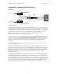
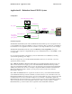
Application #2 - Redundant Smart-UPS XL System
Configuration
Power to
Redundant Switch
Smart-UPS XL "A"
Smart-UPS XL "B"
AC - phase 1
AC - phase 1
or independent
phase (phase 2)
communications
communications
A
B
B
A
Redundant
Switch
Power
to Load
communications
EPO
Emergency
Power Off
R
T
N
I
N
+
2
4
Function
StatusSelect
StatusSelect
To UPS BAC SourceTo UPS A
B
A
Level
Source selectedBright
Source OK, but not selectedDim
Source not OKOff
To Server
Redundant Switch
Smart-UPS XL Battery Pack(s)
Goals and objectives
The Redundant Smart-UPS System created with Redundant Switch enables provides very high level of AC
power availability and continuous availability of safe server shutdown. This very high level of availability is
recommended for server applications where the downtime costs are high and data recovery time is lengthy.
The Redundant Smart-UPS System adds a level of redundancy and hot swappability to the power
protection system compared to a single UPS. This provides a substantial increase to system MTBF over that
of a single UPS.
Use of an extended run battery configuration provides an additional level of availability by extending
system ridethrough during power outages.
The user can supply AC power to the Redundant Smart-UPS System from one AC circuit, or from two
separate AC circuits (or phases).
Case 1. One AC Circuit: The Redundant Smart-UPS system has full Smart-UPS redundancy in the case
where one AC circuit is used to supply power to both Smart-UPS units. Redundant Switch proactively
engages the redundant Smart-UPS to deliver power to the load when it senses that the selected Smart-UPS
will drop the load. The user can remove and replace a single Smart-UPS unit while the redundant Smart-
UPS unit and Redundant Switch continue to provide power protection and safe server shutdown
functionality to the loads.
Case 2. Two AC Circuits: When two separate AC circuits are used to power the Redundant Smart-UPS
System, Redundant Switch provides the redundancy as described in Case 1, above. In addition to this, the
Redundant Smart-UPS System offers users the option of specifying which AC source powers the loads. This
is useful when there is a need for scheduled downtime of one AC circuit or Smart-UPS. Configure the
Redundant Switch (front panel selection) to power the loads from one AC circuit / Smart-UPS combination
while servicing the other AC circuit / Smart-UPS combination. When servicing completes, configure
Redundant Switch to power the loads from the original AC circuit / Smart-UPS combination.