User’s Manual English APC Smart-UPS 2U Rack and Stack External Battery Pack 990-1022, Revision 1 5/00
Entire contents copyright © 2000 by American Power Conversion Corporation. All rights reserved. Reproduction in whole or in part without permission is prohibited. APC, Smart-UPS, and PowerChute are registered trademarks of American Power Conversion Corporation. All other trademarks are the property of their respective owners.
Table of Contents Chapter 1: Safety Information..............................................................1 Conventions Used in this Manual..........................................................1 Handling Safety .....................................................................................1 Electrical Safety.....................................................................................2 Deenergizing Safety ..............................................................................
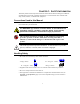
CHAPTER 1: SAFETY INFORMATION This Safety Guide contains important instructions that should be followed during the installation and maintenance of the APC equipment and batteries. It is intended for APC customers who setup, install, relocate, or maintain APC equipment. Conventions Used in this Manual This section defines the symbols used throughout this manual. Carefully read all information boxes and abide by the instructions. The WARNING sign denotes a serious hazard.
Electrical Safety • To reduce the risk of fire, connect only to a circuit provided with a 20 Amp maximum branch circuit overcurrent protection in accordance with the National Electrical Code ANSI/NFPA. • Do not work alone under hazardous conditions. • Check that the power cord(s), plug(s), and sockets are in good condition. Deenergizing Safety • If the equipment has an internal energy source (the battery), the output may be energized when the unit is not connected to an AC power outlet.
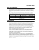
CHAPTER 2: BASICS About Your Battery Pack This APC 2U Rack and Stack Battery Pack is designed to connect to an APC Uninterruptible Power Supply (UPS) to provide extended protection from electrical blackouts, brownouts, sags, and surges. This protection safeguards your computer and other valuable electronic equipment. The external battery pack also provides extra protection while the batteries in the UPS are being replaced.
How To Contact APC Internet http://www.apcc.com/contact North America Phone Fax 1.800.800.4272 1.401.788.2743 Latin America Argentina Brazil Colombia Mexico Uruguay Venezuela Email 0800.9.APCC (0800.9.2722) 0800.12.72.21 980.15.39.47 95.800.804.4283 000.413.598.2139 8001.2856 apctchla@apcc.com If you ordered a Smart-UPS SU1400RMXL3UX171 unit, please refer to the red addendum sheet (part number 990-1023) for contact information.
CHAPTER 3: INSTALLING YOUR BATTERY PACK Unpacking APC has taken care to design robust packaging for your product. However, accidents and damage may occur during shipment. Inspection Inspect the UPS upon receipt. Notify the carrier and dealer if there is damage. The packaging is recyclable; save it for reuse or dispose of it properly.
Place The Battery Pack Where It Will Be Used The battery pack requires two people to install due to its weight. To lighten the battery pack, you may remove the batteries while you position the battery pack or mount it in the rack. Refer to Replacing the Battery, page 15, for instructions on how to remove the batteries. • Battery packs are heavy. Select a location sturdy enough to handle the weight. For rack mounting, install the battery pack at or near the bottom of the rack. Position it below the UPS.
To Mount the Battery Pack in a Rack The battery pack comes with standard 19-inch (46.5 cm) rack mount brackets (in the literature kit) and mounting rails and cleats. There are three steps to install the battery pack in a rack. Each step is explained in this section. 1. Install the mounting rails in the rack. 2. Attach the mounting brackets to the battery pack. 3. Slide the battery pack into the rack and fasten the mounting brackets.
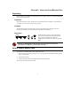
Attach the Mounting Brackets to the Battery Pack • Each mounting bracket attaches to the battery pack with four (4) screws, included. • Two sets of bracket holes are located on the sides of the battery pack. Attach the mounting brackets in the forward position for a four-post rack or the setback position for a two-post rack.
Slide the Battery Pack in the Rack Due to the weight of the battery pack, two people are required to install it in the rack. 1. Using the handles on the side of the battery pack, carefully align the unit with the rails. Slide the battery pack into position. 2. Each side of the battery pack has a cleat that must slide into the groove on the rails. Slide the battery pack into position. 3.
Connect the Battery Pack(s) to the Smart-UPS Battery pack connectors are color coded and keyed to prevent improper connection. The color of the connector on the UPS must match the color of the battery pack connector. Allow the battery pack to charge for 24 hours. Do not expect full run time during this initial charge period. Refer to About Your Battery Pack, page 3, for the type of UPS that supports this battery pack and the maximum number of battery packs that can be connected to a UPS. 1.
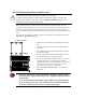
CHAPTER 4: OPERATING THE SMART-UPS Connectors on the Battery Pack The front panel of the battery pack contains a simple bezel (for identification). The optional rack mounting brackets attach to the sides of the battery pack. The rear panel has the connector cable. Front Panel BATTERY PAC K Rear Panel Battery Pack Connector Use the battery pack connector to daisy-chain multiple battery packs to the same UPS. The connector is color-coded and keyed to prevent improper connection.
How to Set the Smart-UPS to Recognize the Battery Pack(s) Smart-UPS XL models cannot determine how many external battery packs are connected to them. You must program the Smart-UPS XL with the appropriate number of external batteries in one of four ways. It is important to follow these instructions. The number of batteries affects the run time calculations which Smart-UPS performs when it is running on battery power.
Use the Terminal Program to Change the Number of External Battery Packs Terminal is used in Windows 3.1x, Windows for Workgroups, and Windows NT 3.51. 1. EXIT out of the PowerChute plus Server. In the case of Windows NT, the UPS Service must be stopped. 2. Go to: Program Manager > Accessories > Terminal. Double-click on the Terminal icon. 3. Select the COM port to which the black-colored interface cable is attached as the Connector. 4.
Use the HyperTerminal Program to Change the Number of External Battery Packs HyperTerminal is used for Windows 95, Windows 98, and Windows NT 4.0 1. EXIT out of the PowerChute plus Server. In the case of Windows NT, the UPS service must be stopped. 2. From the Desktop, go to: Start => Programs => Accessories => HyperTerminal. Doubleclick on the HyperTerminal icon. 3. You are prompted to choose a name and select an icon. Give any name and then click OK. If a message appears which reads “...
CHAPTER 5: MAINTENANCE AND TROUBLESHOOTING Storage Storage Conditions Store the battery pack covered and flat (rack mount orientation) in a cool, dry location, with its battery fully charged. Disconnect any cables connected to the computer interface port to avoid unnecessarily draining the battery. Extended Storage At -15 to +30 °C (+5 to +86 °F), charge the batteries every six months. At +30 to +45 °C (+86 to +113 °F), charge the batteries every three months.
1. Face the front of the battery pack and, using both hands, insert each index finger behind the lip of the curved section of the front bezel and pull towards you. The front bezel will unsnap. 2. Set the bezel aside. The two battery compartments will be visible. 3. Use a screwdriver or coin to remove the two (2) screws and open the door. The door is hinged in the center of the chassis. 4. Take out the white cord, which is tucked into the space above the battery tray handle.
Service If the battery pack requires service do not return it to the dealer! Follow these steps: 1. Verify that no circuit breakers are tripped. A tripped circuit breaker is the most common problem! 2. If the problem persists, call customer service or visit the APC Internet Website (www.apcc.com). • 3. Note the model number of the battery pack, the serial number, and the date purchased. A technician will ask you to describe the problem and try to solve it over the phone, if possible.
18
APPENDIX A: SPECIFICATIONS 2U Battery Pack (SU24RMXLBP2U) Battery type Spill proof, maintenance free, sealed lead-acid Typical battery life 3 – 6 years, depending on number of discharge cycles and ambient temperature Operating temperature 0 to +40 ºC (+32 to +104 ºF) Storage temperature -15 to +45 ºC (+5 to +113 ºF) Operating and storage relative humidity 0 to 95%, non-condensing Operating elevation 0 to +3,000 m (0 to +10,000 ft) Storage elevation 0 to +15,000 m (0 to +50,000 ft) Size (H x W