Smart-UPS® XL Uninterruptible Power Supply Rack-Mount 3U SUA2200/3000 VA 120/230 Vac SUA3000 VA 100/200 Vac English 990-2404B 11/2008
Introduction Introduction About this UPS The APC Uninterruptible Power Supply (UPS) provides protection for electronic equipment from utility power blackouts, brownouts, sags and surges. The UPS filters small utility line fluctuations and isolates electronic equipment from large disturbances by internally disconnecting from utility line power. The UPS provides continuous power from the batteries until utility power returns to safe levels or the batteries are fully discharged.
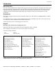
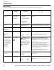
Specifications Specifications Environmental Temperature Operating Storage This unit is intended for indoor use only. Select a location sturdy enough to handle the weight. Do not operate the UPS where there is excessive dust or the temperature or humidity are outside the specified limits.
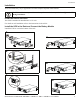
Installation Installation Your UPS model may vary in appearance from the examples depicted in this manual. The UPS and the battery modules are heavy. Remove the battery modules to lighten the UPS during installation. Install the Rails in the Rack This UPS is intended for installation in a 19” rack. For details on rail installation refer to the instructions in the rail kit. Install the UPS in the Rack and Connect the Battery Module Install the UPS at or near the bottom of the rack.
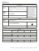
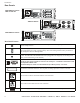
Installation Rear Panels 2200/3000 VA 120 Vac 3000 VA 100 Vac 3000 VA 200 Vac TV S S G ND 2200/3000 VA 230 Vac Rear Panel Features The UPS features a TVSS screw located on the rear panel for connecting the ground leads on transient voltage devices. The UPS is equipped with an external battery connector located on the rear panel of the unit. Where appropriate use an APC extension battery cable. For ordering details contact your dealer or APC through the Web site www.apc.com.
Start-up and Operation Connect equipment, external battery pack(s), and power to the UPS Prior to connecting the grounding cable, ensure that the UPS is NOT connected to utility or battery power. 1. Connect equipment to the UPS. 2. Optional external battery packs provide extended runtime during power outages. This unit supports up to ten external battery packs. Refer to the APC Web site, www.apc.com for information. Refer to the user manual for the external battery pack for installation instructions. 3.
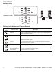
Start-up and Operation Display Panels 120 V models 100/200/230 V models Load / Battery Charge / Display Panel Indicators and Function Buttons Indicator LED 8 Indicator Title Description AVR Trim The UPS is compensating for a high utility voltage. Refer to the APC Web site, www.apc.com for AVR settings. On Line The UPS is supplying utility power to the connected equipment, (see Troubleshooting in this manual). AVR Boost The UPS is compensating for a low utility voltage.
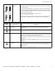
Start-up and Operation 120 V 230 V Battery Charge 100 V Feature Button 200 V Diagnostic Utility The UPS has a diagnostic feature that indicates the utility voltage. Voltage The UPS starts a self-test as part of this procedure. The self-test does not affect the voltage display. Press and hold the Test button to view the utility voltage bar graph indicator.
Configuration Configuration UPS settings Settings are adjusted through PowerChute software or optional SmartSlot accessory cards. Function Factory Default User Selectable Choices Description Automatic Self-Test On startup and every 14 days (336 hours) there after • Every 7 days (168 hours) • On startup and every 14 days (336 hours) there after • On startup only • No self-test Set the interval at which the UPS will execute a self-test.
Configuration Function Low Battery Warning PowerChute software interface provides automatic, unattended shutdown when approximately two minutes of battery operated run time remains.
Configuration Function Low Transfer Point Factory Default 100 V models: 92 Vac 120 V models: 106 Vac 200 V models: 184 Vac 230 V models: 208 Vac Output Voltage 230 V models 230 Vac User Selectable Choices • 86 Vac • 88 Vac • 90 Vac • 92 Vac • 97 Vac • 100 Vac • 103 Vac • 106 Vac • 173 Vac • 176 Vac • 180 Vac • 184 Vac • 196 Vac • 200 Vac • 204 Vac • 208 Vac • 220 Vac • 240 Vac Description To avoid unnecessary use of the battery where utility voltage is chronically low, set the low transfer p
Configuration Configure UPS parameters This configuration affects the accuracy of the predicted runtime calculations the UPS performs while running on battery power. Smart-UPS XL models must be programed to recognize the number of external battery packs connected to the UPS. There are five options available for configuring the UPS to recognize the number of external battery packs 1. 2. 3. 4. 5.
Configuration 3. Press 1 and ENTER to select Device Manager. Select the model by entering the corresponding number, then press ENTER. 4. Press 3 and ENTER to select Configuration. 5. Press 1 and ENTER to select Battery. 6. Press 2 and ENTER to change Battery Settings. 7. Type in the number of external battery packs then press ENTER. Number of external battery packs: 1=1 external battery pack; 2=2 external battery packs; 3=3 external battery packs etc. 8. Press 3 and ENTER to accept the changes. 9.
Maintenance, Transport, and Service Maintenance, Transport, and Service Replacing the Battery Module This UPS has a replacable, hot-swappable battery module. Replacement is a safe procedure, isolated from electrical hazards. Leave the UPS and connected equipment on during the replacement procedure. Once the batteries have been disconnected the connected equipment is not protected from power outages. Refer to the appropriate replacement battery user manual for battery module installation instructions.
Troubleshooting Troubleshooting Use this table to solve minor UPS installation and operation problems. Refer to www.apc.com for assistance with complex UPS problems. Problem and/or Possible Cause Solution UPS will not turn on The battery is not connected properly. Check that the battery connector is fully engaged. Test button not pushed. Press the Test button once to power-up the UPS and connected equipment. The UPS is not connected to utility power supply.
Troubleshooting Problem and/or Possible Cause Solution The Overload LED is illuminated and the UPS emits a sustained alarm tone The UPS is overloaded. The connected equipment exceeds the specified “maximum load” as defined in Specifications on the APC Web site, www.apc.com. The alarm remains on until the overload is removed. Disconnect nonessential equipment from the UPS to eliminate the overload condition.
Troubleshooting Problem and/or Possible Cause Solution There is no utility power There is no utility power and the UPS is off. 120/230 V models only: Use the cold start feature to supply power to the connected equipment front the UPS battery(s). Press and hold the Test button. There will be a short beep followed by a longer beep. Release the button during the second beep. UPS operates on battery although line voltage exists The UPS input circuit breaker trips.
Regulatory and Warranty Information Regulatory and Warranty Information Regulatory Agency Approvals and Radio Frequency Warnings FCC Compliance Notice This equipment has been tested and found to comply with the limits for a Class A digital device, pursuant to part 15 of the FCC Rules. These limits are designed to provide reasonable protection against harmful interference when the equipment is operated in a commercial environment. This equipment generates, uses, and can radiate radio frequency energy.
Two-Year Limited Warranty Two-Year Limited Warranty The limited warranty provided by American Power Conversion (APC®) in this statement of Limited Factory Warranty applies only to products you purchase for your commercial or industrial use in the ordinary course of your business. Terms of warranty APC warrants its products to be free from defects in materials and workmanship for a period of two years from the date of purchase.
Two-Year Limited Warranty Date of product declaration Smart-UPS XL 3U Rack Mount 2200/3000 VA 120/230 Vac; 3000 VA 100/200 Vac User Manual 21
Two-Year Limited Warranty APC Worldwide Customer Support Customer support for this or any other APC product is available at no charge in any of the following ways: • Refer to the APC Web site to access documents in the APC Knowledge Base and to submit customer support requests. – www.apc.com (Corporate Headquarters) Connect to localized APC Web sites for specific countries, each of which provides customer support information. – www.apc.