Smart-UPS DP Uninterruptible Power Supply Models SUDP4000I, SUDP6000I, SUDP8000I, SUDP10000I Service Manual 990-1008, Revision 1, 4/99
Entire contents copyright ©1999 by American Power Conversion. All rights reserved. Reproduction in whole 2 or in part without permission is prohibited Smart-UPS is a registered trademark of APC. All other trademarks are the property of their respective owners.
Table of Contents 1. Introduction....................................................................................................................................... 1 2. Functional Description..................................................................................................................... 4 3. Mechanical Layout ........................................................................................................................... 6 4. Main Diagram .................................
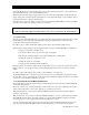
1. Introduction Smart-UPS DP Service procedures should only be performed by authorized electricians or personnel who have been specifically trained to service Smart-UPS DP systems. Whenever AC and/or DC voltage is applied there may be AC voltage at the UPS output, because the UPS can supply output power from mains and from its batteries. To avoid equipment damage or personal injury, always assume that there may be voltage at the UPS output.
extraordinary unforeseen expenses, as a service contract can include all necessary extraordinary services and repairs. For further information, please contact your local APC company, or APC partner. 1.3 Replacement and Maintenance Program Experience shows that some electromechanical and electrical components are exposed to loads, which cause wear and tear and limited life.
1.
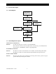
2. Functional Description 2.1 Functional Description 2.1.1 Block Diagram MAINS INPUT CONNECTIONS BACK FEED CONTACTOR BOOST/BUCK CONVERTER BATTERY BYPASS STATIC SWITCH MAIN INVERTER OUTPUT CURRENT SENSOR SYSTEM OUTPUT 2.1.2 Block Diagram Description MAINS INPUT CONNECTIONS Function: To ensure safe and proper connection of the Smart-UPS DP. This is the mains connection of the unit. The mains is connected via power terminals. This is also the location of the RFI-filters, which are supplying the PSU.
BOOST/BUCK CONVERTER Function: The boost/buck converter controls the power factor and regulates the input current. The boost/buck converter makes up for any difference between the output of the Smart-UPS DP and the mains voltage. The boost/buck converter is an electronic choke and works as such. Therefore, the boost/buck converter has a huge internal resistance. Contrary to this, the main inverter is controlled as a constant voltage generator and has, therefore, a very low internal resistance.
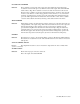
3. Mechanical Layout ) 0 DLQV ) 0DLQV W RU3 P R& W RU3 P R& )25 %$77(5< 7(03 6(1625 )25 (;7( 51$/ 75 7+ 6: ,7&+ 0%6 &21752/ &20 )$8/7 %/$&. 5(' ,1 7(51 $/ %$77 7(03 6(1625 )25 (;7( 51$/ %$77 7(0 3 6(1625 '$1*(5 '$1*(5 +,*+ 92/7$*( +,*+ 92/7$*( 6(( ,167$/ /$7,2 1 ,16 758&7,216 %()25( &211(&7,1* 72 (;7(51$ / % $77(5< ([W %DWWHU \ / / 1 1 9 '& 287387 ,1387 ,1387 ,1387 3 12 7<3( 7<3( 287387 .
Front view Side view only battery modules 7 990-1008, Revision 1, 4/99
4.
9 990-1008, Revision 1, 4/99
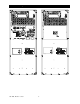
5. Spare Part Lists 5.1 SUDP4000I Part No. Description Item Level Qty. 0017202 Fuse 32A 400Vdc AM 1 10 0017069 Fuse 40A F 600V 1 10 0017067 Fuse 25A 500V FF 1 10 0017017 Fuse 2,5A T 250V 1 10 0017006 Fuse 315mA F 250V 1 10 0017007 Fuse 500mA T 250V 1 10 0017019 Fuse 5A F 500V 1 10 0020035 Fan 2 2 0400793 Control & User IF 3 1 0400763 Power IF 3 1 0400768 Meas & Supply 3 1 0400749 LED - display 3 1 0400750 Temp.
5.2 SUDP6000I Part No. Description Item Level Qty. 0017202 Fuse 32A 400Vdc AM 1 10 0017070 Fuse 16A F 600V 1 10 0017067 Fuse 25A 500V FF 1 10 0017017 Fuse 2,5A T 250V 1 10 0017006 Fuse 315mA F 250V 1 10 0017007 Fuse 500mA T 250V 1 10 0017019 Fuse 5A F 500V 1 10 0017070 Fuse 16A FF 400V 1 10 0020035 Fan 2 2 0400793 Control & User IF 3 1 0400766 Power IF 3 1 0400768 Meas & Supply 3 1 0400749 LED - display 3 1 0400750 Temp.
5.3 SUDP8000I Part No. Description Item Level Qty. 0017202 Fuse 32A 400Vdc AM 1 10 0017069 Fuse 40A F 600V 1 10 0017067 Fuse 25A 500V FF 1 10 0017017 Fuse 2,5A T 250V 1 10 0017006 Fuse 315mA F 250V 1 10 0017007 Fuse 500mA T 250V 1 10 0017019 Fuse 5A F 500V 1 10 0020035 Fan 2 2 0400793 Control & User IF 3 1 0400766 Power IF 3 1 0400768 Meas & Supply 3 1 0400749 LED - display 3 1 0400750 Temp.
5.4 SUDP10000I Part No. Description Item Level Qty. 0901312 Sub. Ass. PU DP100E 3 2 0400739 Control & User IF 2 1 0400740 Power IF 2 1 0400751 Meas & Supply 2 1 0400749 LED - display 2 1 0400750 Temp.
6. Troubleshooting 6.1 Smart-UPS DP does not start START YES MAINS APPLIED? NO NO CONNECT MAINS YES YES YESF001 MCCB ON? SWITCH ON UPS, IS PROBLEM SOLVED? YES NO NO SWITCH OFF F001 AND THEN ON AGAIN SWITCH ON F001 YES IS START-UP SEQUENCE PERFORMED? YES IS START-UP SEQUENCE PERFORMED? YES OPEN UPS NO &+(&.
6.2 Smart-UPS DP does not start. Mains connected and start-up sequence is performed. Smart-UPS DP is open. START ARE FANS OPERATING? NO VOLTAGE ON FAN? YES IS TEMP SWITCH ON HEAT SINK IN PU MOUNTED AND OKAY? NO CORRECT FAULT YES NO IS JUMPER MOUNTED ON REAR SIDE OF UPS? YES NO FAULT IN PSU. CHECK FUSES ON MEAS.
6.3 Smart-UPS DP only operates 5 seconds after start-up. “Undervoltage Timer” active. START DC ON POWER UNIT? NO BATTERY FUSES DEFECTED YES DC FUSES ON PU OKAY? YES INVERTER FUSES OKAY? NO CROWBAR HAS PROBABLY BEEN ACTIVATED YES CORRECT OUTPUT VOLTAGE? YES NO NO CHECK THAT NONE OF THE PINS ON THE THREE 64-POLE PLUGS ARE BENT AND THAT CONNECTION IT OKAY. FAULT IN CONTROLLER PROBABLY BLOWN FUSES IN POWER UNIT(S) CHECK CIRCUIT IN CONNECTION WITH MEASURING OF CHARGE CURRENT, RELAYS, AND IGBT’S.
6.4 Smart-UPS DP not able to switch to normal operation. START IS MAINS OKAY? VOLTAGE FREQ... WAVEFORM? YES POSSIBILITY OF CONNECTING E.G. DPM OR CALIBRATION SW TO UPS? YES IS MAINS OKAY? STEP 86 IN CALIBRATION SW. YES NO NO MAINS OUTSIDE TOLERENCE CHECK SIGNAL FROM MEAS. & SUPPLY TO CONTROLLER iN 64-POLE PLUG FAULT IN 64-POLE PLUG BETWEEN CONTROLLER AND MEAS. & SUPPLY. CHANGE MEAS. & SUPPLY. YES CORRECT SIGNAL? FAULT IN CONTROLLER NO FUSES IN MEAS. & SUPPLY OR MEAS.
6.5 Smart-UPS DP is running in normal operation and mounted with Service Bypass Panel. Service Bypass Panel is not operating. START DOES UPS SWITCH TO BYPASS OPERATION WHEN S002 ON SERVICE BYPASS PANEL IS PUSHED IS IT POSSIBLE TO SWITCH Q002 TO BYPASS YES NO NO IS MAINS WITHIN LIMITS FOR BYPASS OPERATION NO UPS IS NOT ABLE TO OPERATE SERVICE BYPASS PANEL YES CHECK FUSES ON MEAS.
6.
7. Changing Modules This chapter contains instructions for performing the following procedures: Note: If the Smart-UPS DP has been installed with a service bypass panel, the load must be switched over to mains before any of the following procedures can be performed. 7.1 Switching off the Smart-UPS DP 7.2 Removing the cover placed above the external connections 7.3 Removing the external DC-supply 7.4 Opening the Smart-UPS DP 7.5 Removing the internal DC-supply 7.6 Removing cables for external units 7.
7.1 Switching Off the Smart-UPS DP A possible load must be switched off, or switched over to the mains via the service bypass panel. 1. Switch off the Smart-UPS DP on the front of the system. 2. Switch off MCCB (F001) on the rear side of the system. 3. Switch off mains supply to the Smart-UPS DP.
7.2 Removing the Cover Placed Above the External Connections 1. Switch off the Smart-UPS DP (7.1). 2. Remove the screw. 3. Lift the cover upwards and pull out. 4. Make sure that there is no AC-voltage on in- and output of the Smart-UPS DP. ) 0 DLQV ) 0DLQV WU 3R P R& WU 3R P R& )25 %$77(5< 7(03 6(1625 )25 (;7( 51$/ 75 7+ 6: ,7&+ 7(03 6(1625 %/$&.
7.3 Removing the External DC-Supply Switch off external battery switch and remove external battery fuse. 1. Switch off the Smart-UPS DP (7.1). 2. Remove the cover (7.2). 3. Remove the cable relief.. 4. Remove the DC-connector. 5. Remove the earth connection. WARNING HIGH VOLTAGE! Safety precautions for working with high voltage must be kept. ) 0DLQV UWR 3 P R& )25 %$77(5< 7(03 6(1625 )25 (;7( 51$/ 75 7+ 6:,7&+ 0%6 &21752/ &20 )$8/7 %/$&.
7.4 Opening the Smart-UPS DP 1. Switch off the Smart-UPS DP (7.1). 2. Remove the cover (7.2). 3. Remove the external DC-Supply (7.3). 4. Remove the screws on rear side of the system that hold the cover on. 5. Remove the cover by sliding the rear end of the cover upwards and back. WARNING Take care not to drop the front edge of the cover into the power unit.
7.5 Removing the Internal DC-Supply 1. Switch off the Smart-UPS DP (7.1). 2. Remove the cover (7.2). 3. Remove the external DC-Supply (7.3). 4. Open the Smart-UPS DP (7.4). 5. Remove the battery plug from the middle plate below the electronic shelf. 6. Using isolated fuse tongs, remove the battery fuses. WARNING HIGH VOLTAGE! Safety precautions for working with high voltage must be kept. 7.
7.6 Removing Cables for External Units 1. Switch off the Smart-UPS DP (7.1). 2. Remove the cover (7.2). 3. Remove the external DC-Supply (7.3). 4. Open the Smart-UPS DP (7.4). 5. Remove the internal DC-supply (7.5). 6. Remove the cable relief belonging to the cable being removed. Then choose the cable(s) to be removed. 7. Remove the connector for the internal battery temperature sensor. 8. Remove the connector for the external battery temperature sensor. 9.
7.7 Remove the SmartSlot 1. Switch off the Smart-UPS DP (7.1). 2. Remove the cover (7.2). 3. Remove the external DC-Supply (7.3). 4. Open the Smart-UPS DP (7.4). 5. Remove the internal DC-supply (7.5). 6. Remove the external unit’s cables (7.6). 7. Remove the ribbon cable from the controller board. 8. Remove the earth wires from the option board. 9. Remove the 4 screws connecting the SmartSlot. The SmartSlot is now free.
7.8 Removing the Controller Board 1. Switch off the Smart-UPS DP (7.1). 2. Remove the cover (7.2). 3. Remove the external DC-Supply (7.3). 4. Open the Smart-UPS DP (7.4). 5. Remove the internal DC-supply (7.5). 6. Remove the external unit’s cables (7.6). 7. Remove the SmartSlot (7.7) 8. Remove the 2 (4) screws that connect the CU-board to the PU-board(s). 9. Remove the LED-display ribbon cable. 10. Remove the options ribbon cable. 11. Remove the grounding wire from the chassis.
12. Remove the screw from the back of the system. 13. Loosen screw from the back of the system. ) 0DLQV W RU3 RP & )25 %$77(5< 7(03 6(1625 )25 (;7( 51$/ 75 7+ 6:,7&+ 0%6 &21752/ &20 )$8/7 %/$&. 5(' ,17(51$/ %$77 7(03 6 (1625 )25 (;7( 51$/ %$77 7(03 6(1625 '$1*(5 +,*+ 92/7$*( 6(( ,167$//$7,21 ,16758 &7,21 6 ([W %DWWHU \ %()25( &211(&7,1* 72 / 1 / 1 9 '& (; 7(51$/ %$77(5< ,1387 287387 14.
7.9 Removing the Power Unit Board 2 (Upper) 1. Switch off the Smart-UPS DP (7.1). 2. Remove the cover (7.2). 3. Remove the external DC-Supply (7.3). 4. Open the Smart-UPS DP (7.4). 5. Remove the internal DC-supply (7.5). 6. Remove any cables for external units (7.6). 7. Remove the SmartSlot (7.7). 8. Remove the controller board (7.8). 9. Remove the wires on the power unit terminals X004, X005, X006, X022, X008, and X001, as well as the connector for the fan shelf at X003 A, B, or C. 10.
7.10 Removing the Power Unit Board 1 (Lower) 1. Switch off the Smart-UPS DP (7.1). 2. Remove the cover (7.2). 3. Remove the external DC-Supply (7.3). 4. Open the Smart-UPS DP (7.4). 5. Remove the internal DC-supply (7.5). 6. Remove the external unit cables (7.6). 7. Remove the SmartSlot (7.7). 8. Remove the controller board (7.8). 9. Remove the power unit board 2 (if mounted) (7.9). 10.
13. Remove the stay/screws connecting the board. The board is now free.
7.11 Removing the Power Interface Board 1. Switch off the Smart-UPS DP (7.1). 2. Remove the cover (7.2). 3. Remove the external DC-Supply (7.3). 4. Open the Smart-UPS DP (7.4). 5. Remove the internal DC-supply (7.5). 6. Remove the external unit cables (7.6). 7. Remove the SmartSlot (7.7). 8. Remove the X001, X002, and X004 power interface board connectors. 9. Remove the contactor from the DIN bar.
10. Remove the wires in X005, X006, X007, X008, X009, X010, X025, X026, X027, X028, X015, X016, X017, X018, X019, X020, X021, X022, X023, and X024. 11. Remove the screws connecting the power interface board.
7.12 Removing the Measuring and Supply Board 1. Switch off the Smart-UPS DP (7.1). 2. Remove the cover (7.2). 3. Remove the external DC-Supply (7.3). 4. Open the Smart-UPS DP (7.4). 5. Remove the internal DC-supply (7.5). 6. Remove the external unit cables (7.6). 7. Remove the SmartSlot (7.7). 8. Remove the controller board (7.8). 9. Remove the power interface board (7.11). 10. Remove the stay. 11. Remove the X005 and X006 connectors.
7.13 Removing the Batteries WARNING: HIGH VOLTAGE Safety precautions for working with high voltage must be kept. 1. Switch off the Smart-UPS DP (7.1). 2. Remove the cover (7.2). 3. Remove the external DC-Supply (7.3). 4. Open the Smart-UPS DP (7.4). 5. Remove the internal DC-supply (7.5). 6. Move the shelf above the upper battery slightly upwards and pull it out. 7. Remove the interconnection wire between the two center batteries. 8.
9. Remove the four sections batteries and put them aside, or remove all connecting wires and remove batteries one at a time. Repeat steps 1 to 4 until all batteries are removed. NOTE: The bottom battery section cannot be removed on account of the edge of the chassis. Therefore the battery must be tilted. 10. Move the battery to the side edge. 11. Tilt the battery and remove it.
7.14 Removing the LED- Board 1. Switch off the Smart-UPS DP (7.1). 2. Remove the cover (7.2). 3. Remove the external DC-Supply (7.3). 4. Open the Smart-UPS DP (7.4). 5. Remove the internal DC-supply (7.5). 6. Remove the screw from the board. 7. Loosen the board from the board holder. 8. Tilt the board slightly and remove the ribbon cable connector. The board now is free.
7.15 Removing the Battery Temperature Sensor Board 1. Switch off the Smart-UPS DP (7.1). 2. Remove the cover (7.2). 3. Remove the external DC-Supply (7.3). 4. Open the Smart-UPS DP (7.4). 5. Remove the internal DC-supply (7.5). 6. Remove the external unit cables (7.6) 7. Remove the two screws on the rear side of the system, which keep the board. ) 0DLQV WU R3 P R& )25 %$77(5< 7(03 6(1625 )25 (;7( 51$/ 75 7+ 6:,7&+ 0%6 &21752/ &20 )$8/7 %/$&.
Remove Fan on Electronic Shelf 1. Switch off the Smart-UPS DP (7.1) 2. Remove cover (7.2) 3. Remove external DC-Supply (7.3) 4. Open the Smart-UPS DP (7.4) 5. Remove internal DC-supply (7.5) 6. Remove connector for fan on the power unit board X003 A and/or C. 7. Remove 4 nuts on fan.
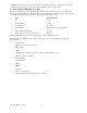
8. Test/Adjustments After Repair 8.1 Test/Adjustments After Repair Calibration of Smart-UPS DP Smart-UPS DP requires the following equipment: • PC containing calibration software as well as calibration interface. • Load, meaning both resistive load, SMPS load, as well as transformer. • Voltmeter. • Ammeter, possibly a current clamp. • Scope, possibly a thermometer on account of temperature sensor. Step refers to Calibration Software. (Test Smart-UPS DP General, 7.100.
Acoustic alarm level (High/Low) Bypass voltage tolerance Output frequency tolerance Automatic battery test (OFF/Number of days) 990-1008, Revision 1, 4/99 42
Checked (ä) * Indicates steps which must always be done. 8.1.1 Check PCB’s and software revisions and updated according to EI’s q 8.1.2 Check that fan is clean and it does not make any noise q 8.1.3 Check stand-by voltage on batteries, (VBATT≥384V = 12.0V/btt.) or change batteries. q 8.1.4 Test Smart-UPS DP General, 7.100.542 and Step Description MPU_CAL1, 7.000.854GB. q Possibly calibrate.
8.1.10 8.1.11 Load the system with 165% (See App.1). Check that: • the system switches to battery operation. • the output current is reduced to 155% +4/-2% (See App.1). • After 30 seconds (±5 sec.) the output current is further reduced to 105 % +4/-2% (See App.1). • The system switches off after 5 seconds. q q q q Switch off the load. Step 32 Enter 1 Step 37 Enter 5 BYON 8.1.12 Check lower switching off level -18% (See App.1). q 8.1.13 Check lower switching on level -9% (See App.1).
8.3 Test of Options Checked (ä) 8.2.1 Check Multicom; communication is tested by means of DP-Monitor (data transmitted). 8.2.2 Check Compower 5/12V. • 5V Compower = 5V±0.3V • 12V Compower = 10V ±1.2V q q q 8.2.3 Check remote display driver, mount remote display, and check the indicators. q 8.2.4 Check transformer module, fan + thermal switch OK. q 8.2.
8.4 APPENDIX 1. Current limitation level Currents in “ A” as a function of output voltage and load in % SUDP4OOOI 100% 18.2 17.4 16.7 105% 19.1 18.3 17.5 110% 20.0 19.1 18.3 155% 28.2 27.0 25.8 165% 30.0 28.7 27.5 100% 27.3 26.1 25.0 105% 28.6 27.4 26.3 110% 30.0 28.7 27.5 155% 42.3 40.4 38.8 165% 45.0 43.0 41.3 100% 36.4 34.8 33.3 105% 38.2 36.5 35.0 110% 40.0 38.3 36.7 155% 56.4 53.9 51.7 165% 60.0 37.4 55.0 100% 45.5 43.5 41.7 105% 47.
Switching ON/ Switching OFF levels Switching ON/OFF 220V 230V 240V Tol. Lower OFF / -18% 180.4V 188.6V 196.8V ±0.5V Lower ON / -9% 200.2V 209.3V 218.4V ±0.5V Upper OFF / +12% 246.4V 257.6V 268.8V ±0.5V Upper ON / +6.5% 243.4V 245.0V 255.6V ±0.5V Output voltage in bypass Tol. 220V 230V 240V ±11.0V ±11.6V ±12.0V 220V 230V 240V ±4.4V ±4.6V ±4.8V Output voltage VNOM Tol.
9.
10.
11.